
Concept explainers
Videos
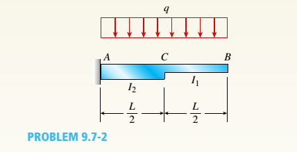
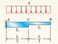
The cantilever beam ACB shown in the figure supports a uniform load of intensity q throughout its length. The beam has moments of inertia I2and IYin parts AC and CB, respectively.
- Using the method of superposition, determine the deflection SBat the free end due to the uniform load.
a.
The deflectiony13
Answer to Problem 9.7.2P
The deflectiony1313
Explanation of Solution
Given:
We have the data,
Length of the beam ACB as, L
Intensity of uniform load, q
Moment of inertia of,
Moment of inertia of,
Concept Used:
The cantilever beam ACB as per the below figure supports a uniform load of intensity q throughout its length with moments of inertia

Calculation:
We have the below diagram for part CB as below.
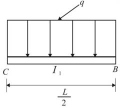
Deflection at point B would be calculated as,
We have the below diagram for part AC as below.
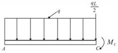
The moment at point C,
The deflection at point C can be calculated as below.
Angle of rotation at point C can be determined as,
At point B, the deflection would be,
Therefore, the total deflection at point B would be,
Conclusion:
The deflection
b.
The ratio r of the deflection
Answer to Problem 9.7.2P
The ratio r is
Explanation of Solution
Given:
We have the data,
Length of the beam, L
Moment of inertia of,
Moment of inertia of,
Load at point B, P
Concept Used:
The cantilever beam ACB as per the below figure supports a uniform load of intensity q throughout its length with moments of inertia
Calculation:
For the prismatic cantilever beam, we have
We can calculate the ratio as below.
Conclusion:
The ratio r is calculated using the cantilever beam concept and moment diagram.
c.
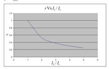
To plot : A graph for the deflection ratio (r) versus the ratio
Explanation of Solution
Given:
We have the data,
Length of the beam, L
Moment of inertia of,
Moment of inertia of,
Load at point B, P
Concept Used:
The cantilever beam ACB as per the below figure supports a uniform load of intensity q throughout its length with moments of inertia

Calculation:
The values for plotting graph are shown in below table:
| r | |
| 1 | 1 |
| 2 | 0.53 |
| 3 | 0.38 |
| 4 | 0.3 |
| 5 | 0.25 |
We will get graph as shown below:

Conclusion:
The graph for the deflection ratio (r) versus the ratio
Want to see more full solutions like this?
Chapter 9 Solutions
Mechanics of Materials (MindTap Course List)


- For the beam show below, draw A.F.D, S.F.D, B.M.D 6 kN/m 1 M B. 3 M Marrow_forward1. Two long rods of the same diameter-one made of brass (k=85w/m.k) and the other made of copper (k=375 w/m.k) have one of their ends inserted into a furnace (as shown in the following figure). Both rods are exposed to the same environment. At a distance of 105 mm from the furnace, the temperature of the brass rod is 120°C. At what distance from the furnace will the same temperature be reached in the copper rod? Furnace 105 mm T₁ Brass rod ⑪ h Too- x2- Ti Copper rodarrow_forward: +0 العنوان use only Two rods fins) having same dimensions, one made orass (k = 85 Wm K) and the mer of copper (k = 375 W/m K), having of their ends inserted into a furna. At a section 10.5 cm a way from furnace, the temperature of brass rod 120 Find the distance at which the ame temperature would be reached in the per rod ? both ends are ex osed to the same environment. ns 2.05 ۲/۱ ostrararrow_forward
- مشر on ۲/۱ Two rods (fins) having same dimensions, one made of brass(k=85 m K) and the other of copper (k = 375 W/m K), having one of their ends inserted into a furnace. At a section 10.5 cm a way from the furnace, the temperature brass rod 120°C. Find the distance at which the same temperature would be reached in the copper rod ? both ends are exposed to the same environment. 22.05 ofthearrow_forwardThe composite wall of oven with A= 1m² as in Fig.1 consists of three materials, two of with kA = 20 W/m K and kc = 50 W/m K with thickness, LA=0.3 m, L= 0.15 m and Lc 0.15 m. The inner surface temperature T1=900 K and the outer surface temperature T4 300 K, and an oven air temperature of To=1100 K, h=25 W/m². K. Determine kɛ and the temperatures T2 and T3 also draw the thermal resistance networkarrow_forwardTwo rods (fins) having same dimensions, one made of brass (k = 85 Wm K) and the other of copper (k = 375 W/m K), having one of their ends inserted into a furnace. At a section 10.5 cm a way from the furnace, the temperature of brass rod 120°C. Find the distance at which the same temperature would be reached in the copper rod ? both ends are exposed to the same environment. Ans 22.05arrow_forward
- A long wire (k-8 W/m °C.) with ro 5 mm and surface temperature Ts=180°C as shown in Fig.2. Heat is generated in the wire uniformly at a rate of 5 x10⁷ W/m³. If the energy equation is given by: d 11(77) + - =0 k r dr dr Derive an expression for T(r) and determine the temperature at the center of the wire and at r=2 mm. Air Th T KA LA T2 T3 T Fig.1 KB kc 180°C Го Fig.2arrow_forwardB: Find the numerical solution for the 2D equation below and calculate the temperature values for each grid point shown in Fig. 2 (show all steps). (Do only one trail using following initial values and show the final matrix) T₂ 0 T3 0 I need a real solution, not artificial intelligence locarrow_forwardCan I solve this problem by calculating the initial kinetic energy with respect to G instead of A.arrow_forward
- B: Find the numerical solution for the 2D equation below and calculate the temperature values for each grid point shown in Fig. 2 (show all steps). (Do only one trail using following initial values and show the final matrix) T₂ 0 T3 0 locarrow_forwardShow all work. Indicate the origin that is used for each plane. Identify the Miller indices for the following planes. N 23 1 A) X B) yarrow_forwardthe following table gives weight gain time data for the oxidation of some metal at an elevated temperature W(mg/cm2). Time (min) 4.66 20 11.7 50 41.1 175 a) determin whether the oxidation kinetics obey a linear, parabolic, or logarithmic rate expression. b) Now compute W after a time of 1000 minarrow_forward
 Mechanics of Materials (MindTap Course List)Mechanical EngineeringISBN:9781337093347Author:Barry J. Goodno, James M. GerePublisher:Cengage Learning