
Concept explainers
Videos
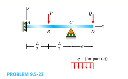
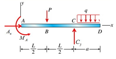
The overhanging beam A BCD supports two concentrated loads P and Q (see figure),
- For what ratio PIQ will the deflection at point B be zero?
- For what ratio will the deflection at point D be zero?
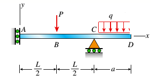
- If Q is replaced by a uniform load with intensity q (on the overhang), repeat parts (a) and (b), but find ratio Pl(qa).
(a)
Ratio P/Q for which deflection at B is zero .
Answer to Problem 9.5.23P
Ratio P/Q for which deflection at B is zero is
Explanation of Solution
Given Information:
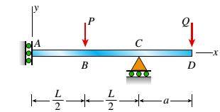
The following figure is given along with relevant information,

The deflection at B is zero.
Calculation:
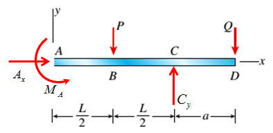
Consider the following free body diagram,
Take equilibrium of forces in horizontal direction as,
Take equilibrium of forces in vertical direction as,
Take equilibrium of moments about A as,
The bending moment at distance x from point A is given by,
The deflection and bending moment is related by following differential equation
Integrate differential equation (1) with respect to x by putting expression for M to get angle of rotations, as,
Integrate angle of rotation with respect to x get deflections as,
The following conditions are used to evaluate integration constants,
Since deflection at B is zero, hence
Now substitute values of constants and solve the above equation to get
Conclusion:
Therefore, the ratio P/Q for which deflection at B is zero is
(b)
Ratio P/Q for which deflection at D is zero .
Answer to Problem 9.5.23P
Ratio P/Q for which deflection at D is zero is
Explanation of Solution
Given Information:
The following figure is given along with relevant information,
The deflection at D is zero.
Calculation:
Consider the following free body diagram,

Take equilibrium of forces in horizontal direction as,
Take equilibrium of forces in vertical direction as,
Take equilibrium of moments about A as,
The bending moment at distance x from point A is given by,
The deflection and bending moment is related by following differential equation
Integrate differential equation (1) with respect to x by putting expression for M to get angle of rotations, as,
Integrate angle of rotation with respect to x get deflections as,
The following conditions are used to evaluate integration constants,
Since deflection at D is zero, hence
Now substitute values of constants and solve the above equation to get
Conclusion:
Therefore, the ratio P/Q for which deflection at D is zero is
(c)
Ratio P/Q for which deflection at B and D is zero .
Answer to Problem 9.5.23P
Explanation of Solution
Given Information:
The following figure is given along with relevant information,
The deflection at B and D is zero.
Calculation:
Consider the following free body diagram,
Take equilibrium of forces in horizontal direction as,
Take equilibrium of forces in vertical direction as,
Take equilibrium of moments about A as,
The bending moment at distance x from point A is given by,
The deflection and bending moment is related by following differential equation
Integrate differential equation (1) with respect to x by putting expression for M to get angle of rotations, as,
Integrate angle of rotation with respect to x get deflections as,
The following conditions are used to evaluate integration constants,
Substitute values of constants to get the expression for deflection.
Since deflection at B is zero, hence
Solve the above equation to get
For deflection at D is zero,
Solve the above equation to get
Conclusion:
Therefore, the ratio P/Q
Want to see more full solutions like this?
Chapter 9 Solutions
Mechanics of Materials (MindTap Course List)


- How do i solve this problem?arrow_forwardQ4/ A compressor is driven motor by mean of a flat belt of thickness 10 mm and a width of 250 mm. The motor pulley is 300 mm diameter and run at 900 rpm and the compressor pulley is 1500 mm diameter. The shaft center distance is 1.5 m. The angle of contact of the smaller pulley is 220° and on the larger pulley is 270°. The coefficient of friction between the belt and the small pulley is 0.3, and between the belt and the large pulley is 0.25. The maximum allowable belt stress is 2 MPa and the belt density is 970 kg/m³. (a) What is the power capacity of the drive and (b) If the small pulley replaced by V-grooved pulley of diameter 300 mm, grooved angle of 34° and the coefficient of friction between belt and grooved pulley is 0.35. What will be the power capacity in this case, assuming that the diameter of the large pulley remain the same of 1500 mm.arrow_forwardYou are tasked with designing a power drive system to transmit power between a motor and a conveyor belt in a manufacturing facility as illustrated in figure. The design must ensure efficient power transmission, reliability, and safety. Given the following specifications and constraints, design drive system for this application: Specifications: Motor Power: The electric motor provides 10 kW of power at 1,500 RPM. Output Speed: The output shaft should rotate at 150 rpm. Design Decisions: Transmission ratio: Determine the necessary drive ratio for the system. Shaft Diameter: Design the shafts for both the motor and the conveyor end. Material Selection: Choose appropriate materials for the gears, shafts. Bearings: Select suitable rolling element bearings. Constraints: Space Limitation: The available space for the gear drive system is limited to a 1-meter-long section. Attribute 4 of CEP Depth of knowledge required Fundamentals-based, first principles analytical approach…arrow_forward
- - | العنوان In non-continuous dieless drawing process for copper tube as shown in Fig. (1), take the following data: Do-20mm, to=3mm, D=12mm, ti/to=0.6 and v.-15mm/s. Calculate: (1) area reduction RA, (2) drawing velocity v. Knowing that: ti: final thickness V. Fig. (1) ofthrearrow_forwardA direct extrusion operation produces the cross section shown in Fig. (2) from an aluminum billet whose diameter 160 mm and length - 700 mm. Determine the length of the extruded section at the end of the operation if the die angle -14° 60 X Fig. (2) Note: all dimensions in mm.arrow_forwardFor hot rolling processes, show that the average strain rate can be given as: = (1+5)√RdIn(+1)arrow_forward
- : +0 usão العنوان on to A vertical true centrifugal casting process is used to produce bushings that are 250 mm long and 200 mm in outside diameter. If the rotational speed during solidification is 500 rev/min, determine the inside radii at the top and bottom of the bushing if R-2R. Take: -9.81 mis ۲/۱ ostrararrow_forward: +0 العنوان use only In conventional drawing of a stainless steel wire, the original diameter D.-3mm, the area reduction at each die stand r-40%, and the proposed final diameter D.-0.5mm, how many die stands are required to complete this process. онarrow_forwardIn non-continuous dieless drawing process for copper tube as shown in Fig. (1), take the following data: Do-20mm, to=3mm, D=12mm, ti/to=0.6 and vo-15mm/s. Calculate: (1) area reduction RA, (2) drawing velocity v. Knowing that: t₁: final thickness D₁ V. Fig. (1) Darrow_forward
- A vertical true centrifugal casting process is used to produce bushings that are 250 mm long and 200 mm in outside diameter. If the rotational speed during solidification is 500 rev/min, determine the inside radii at the top and bottom of the bushing if R-2Rb. Take: 8-9.81 m/sarrow_forwardIn conventional drawing of a stainless steel wire, the original diameter D.-3mm, the area reduction at each die stand r-40%, and the proposed final diameter D₁-0.5mm, how many die stands are required to complete this process.arrow_forwardA vertical true centrifugal casting process is used to produce bushings that are 250 mm long and 200 mm in outside diameter. If the rotational speed during solidification is 500 rev/min, determine the inside radii at the top and bottom of the bushing if R-2Rb. Take: 8-9.81 m/sarrow_forward
 Mechanics of Materials (MindTap Course List)Mechanical EngineeringISBN:9781337093347Author:Barry J. Goodno, James M. GerePublisher:Cengage Learning