Concept explainers
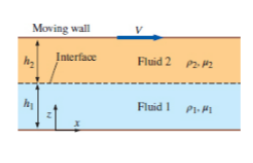
Consider a modified form of Couette flow in which there are two immiscible fluids sandwiched between two infinitely lone and wide, parallel flat plates (Fig. 9-101). The flow is steady, incompressible, parallel, and laminar. The top plate moves at velocity V to the right, and the bottom plate is stationary. Gravity acts in the -z-direction (downward in the figure). There is no forced pressure gradient pushing the fluids through the channel-the flow is setup solely by viscous effects created by the moving upper plate. You may ignore surface tension effects and assume that dre interface is horizontal. The pressure at the bottom of the flow (z = 0) is equal to

FIGURE P9-101
(a)
The six appropriate boundary condition on both velocity and pressure.
Answer to Problem 101P
The first boundary conditions is
The second boundary conditions is
The third boundary conditions is
The fourth boundary conditions is
The fifth boundary conditions is
The sixth boundary conditions is
Explanation of Solution
Given information:
The following figure shows that two parallel flat plates.

Figure-( 1)
Assume, at the point of wall and fluid, the velocity of the fluid is equal to zero.
Write the expression for velocity of the fluid 1,
Here, the velocity of fluid 1 is
Assume, the velocity of the fluid 2 at the free surface of the wall is equal to the velocity of the moving plates.
Write the expressions for the velocity of fluid 2.
Here, the velocity of fluid 2 is
Write the expression for velocity at interface.
Write the expression for rate of shear stress.
Here, the kinematic coefficient of fluid is
Write the expression for the shear stress acting on fluid 1.
Here, the kinematic coefficient of fluid 1 is
Write the expression for the shear stress acting on fluid 2.
Here, the kinematic coefficient of fluid 2 is
Write the expression for the rate of shear stress at interface.
Write the expression for pressure at the bottom of the flow,
Here, the pressure is
Write the expression for the pressure at the interface of fluid 1.
Here, the pressure at the fluid 1 is
Write the expression for the pressure at the interface of fluid 2.
Here, the pressure at the fluid 1 is
Assume, at the interface of the fluid the pressure cannot have discontinuity and the surface is ignored.
Write the expression for the pressure at interface of fluid.
Conclusion:
The first boundary conditions is
The second boundary conditions is
The third boundary conditions is
The fourth boundary conditions is
The fifth boundary conditions is
The sixth boundary conditions is
(b)
The expression for the velocity of fluid 1.
The expression for the velocity of fluid 2.
Answer to Problem 101P
The expression for the velocity of fluid 1 is
The expression for the velocity of fluid 2 is
Explanation of Solution
Write the expression for
Here, the velocity of flow for fluid 1 is
Write the expression for
Here, the velocity of flow for fluid 2 is
Calculation:
Integrate Equation (XIII) with respect to
Here, the constant is
Integrate Equation (XIII) with respect to
Here, the constant is
Integrate Equation (XIV) with respect to
Here, the constant is
Integrate Equation (XIV) with respect to
Here, the constant is
Substitute
Substitute
Substitute
Substitute
Substitute
Differentiate Equation (XXI) with respect to
Substitute
Substitute
Substitute
Substitute
Conclusion:
The expression for the velocity of fluid 1 is
The expression for the velocity of fluid 2 is
(c)
The expression for the pressure of fluid 1.
The expression for the pressure of fluid 2.
Answer to Problem 101P
The expression for the pressure of fluid 1 is
The expression for the pressure of fluid 2 is
Explanation of Solution
Write the expression for
Here, the density of the fluid 1 is
Write the expression for
Here, the density of the fluid 2 is
Calculation:
Integrate Equation (XXV) with respect to
Here, the constant is
Substitute
Substitute
Integrate Equation (XXVI) with respect to
Here, the constant is
Substitute
Substitute
Substitute
Conclusion:
The expression for the pressure of fluid 1 is
The expression for the pressure of fluid 2 is
(d)
The plot
Answer to Problem 101P
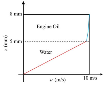
The following Figure-(2) represents the velocities of fluid 1 and 2.

Explanation of Solution
Given information:
The fluid 1 be water and the fluid 2 be unused engine oil, at
The following figure shows that two parallel flat plates.
Write the expression for the velocity of fluid 1.
Here, the distance is
Write the expression for the velocity of fluid 2.
Calculation:
Refer the Table-A-3E, "Properties of saturated water", to obtain the value of dynamic viscosity of water is
Refer the Table-A-7E, "Properties of the atmosphere at high attitude", to obtain the value of dynamic viscosity of unused engine oil is
Substitute
Substitute
The following graph represents the velocities of fluid 1 and 2.

Figure-(2)
In the fluid 1 the linear curve is increasing with respect to the velocity of flow and height of fluid 1. In the fluid 2 the curve is increasing with respect to the velocity of flow and height of fluid 2.
Conclusion:
The following Figure-(2) represents the velocities of fluid 1 and 2.

Want to see more full solutions like this?
Chapter 9 Solutions
FLUID MECHANICS FUNDAMENTALS+APPS
Additional Engineering Textbook Solutions
Heat and Mass Transfer: Fundamentals and Applications
Thermodynamics: An Engineering Approach
Vector Mechanics for Engineers: Statics and Dynamics
DeGarmo's Materials and Processes in Manufacturing
Machine Tool Practices (10th Edition)
Foundations of Materials Science and Engineering
- Consider fully developed Couette flow between two infinite parallel plates separated by distance h, with the top plate moving and the bottom plate stationary, as illustrated in the figure below. The flow is steady, incompressible, and two-dimensional in the XY plane. The velocity field is given by V }i = (u, v) = (v² )i +0j = V (a) Find out the acceleration field of this flow. (b) Is this flow steady? What are the u and v components of velocity? u= V² harrow_forwardConsider the pipe annulus sketched in fig. Assume that the pressure is constant everywhere (there is no forced pressure gradient driving the flow). However, let the inner cylinder be moving at steady velocity V to the right. The outer cylinder is stationary. (This is a kind of axisymmetric Couette flow.) Generate an expression for the x-component of velocity u as a function of r and the other parameters in the problem.arrow_forwardHello sir Muttalibi is a step solution in detailing mathematics the same as an existing step solution EXAMPLE 6-1 Momentum-Flux Correction Factor for Laminar Pipe Flow CV Vavg Consider laminar flow through a very long straight section of round pipe. It is shown in Chap. 8 that the velocity profile through a cross-sectional area of the pipe is parabolic (Fig. 6-15), with the axial velocity component given by r4 V R V = 2V 1 avg R2 (1) where R is the radius of the inner wall of the pipe and Vavg is the average velocity. Calculate the momentum-flux correction factor through a cross sec- tion of the pipe for the case in which the pipe flow represents an outlet of the control volume, as sketched in Fig. 6-15. Assumptions 1 The flow is incompressible and steady. 2 The control volume slices through the pipe normal to the pipe axis, as sketched in Fig. 6-15. Analysis We substitute the given velocity profile for V in Eq. 6-24 and inte- grate, noting that dA, = 2ar dr, FIGURE 6–15 %3D Velocity…arrow_forward
- Consider fully developed two-dimensional Poiseuille flow—flow between two infinite parallel plates separated by distance h, with both the top plate and bottom plate stationary, and a forced pressure gradient dP/dx driving the flow as illustrated in Fig. (dP/dx is constant and negative.) The flow is steady, incompressible, and two-dimensional in the xy-plane. The velocity components are given by u = 1/2? dP/dx (y2 − hy) ? = 0where ?isthefluid’sviscosity.Isthisflowrotationalorirrotational? If it is rotational, calculate the vorticity component in the z-direction. Do fluid particles in this flow rotate clockwise or counterclockwise?arrow_forwardFluid Mechanics Define Flow field ? Define equations not a general definitionarrow_forwardFor each statement, choose whether the statement is true or false, and discuss your answer briefly. (a) The velocity potential function can be defined for threedimensional flows. (b) The vorticity must be zero in order for the stream function to be defined. (c) The vorticity must be zero in order for the velocity potential function to be defined. (d) The stream function can be defined only for two-dimensional flow fields.arrow_forward
- Air flow at a constant speed (Us = 10 m/s) is forming a two-dimensional incompressible laminar boundary layer along a flat plate The velocity profile inside the boundary layer is given by: =2-² A wind tunnel designer plans to build a two dimensional test section for a low speed wind tunnel. The design specification requires that in the test section the free stream flow must be equal to the air velocity at the entrance of the test section. (Figure Q2). U 30 m/s h₁ = 2²-² x,-0.0 Top wall Bottom wall -300 mm X-300 mm Figure Q2 Assuming the same velocity profile as in equation 1, and by using the momentum integral equation determine how much the bottom and top walls should be displaced at point 2 (x₂ = 300 mm) in order to achieve the design requirement as was stated above. In not more than 30-40 words justify your solution. Equation 1:arrow_forwardDefine variable flow? Also discuss the forces encoundered in fluid mechanics?arrow_forwardV u-v Question 4: Consider fully developed Couette flow - flow between two infinite parallel plates separated by distance h, with the top plate moving and the bottom plate stationary as illustrated. The flow is steady, incompressible, and two dimensional in the xy-plane. The velocity field is given by V = (u,v) = (V y/h)ỉ + 0ỷ, Generate an expression for stream function Yalong the vertical dashed line in the figure. For convenience, 4= 0 along the bottom wall of the channel. What is the value of Y along the top wall?arrow_forward
- A flow field is described in Cartesian coordinates by Is it incompressible?arrow_forwardConsider two-dimensional flow in the x-y plane where we are using polar coordinatesr and O to describe the motion. We will call u the radial velocity and v the azimuthal velocity (see figure below). y u Xarrow_forwardA subtle point, often missed by students of fluid mechanics (and even their professors!), is that an inviscid region of flow is not the same as an irrotational (potential) region of flow. Discuss the differences and similarities between these two approximations. Give an example of each.arrow_forward
 Elements Of ElectromagneticsMechanical EngineeringISBN:9780190698614Author:Sadiku, Matthew N. O.Publisher:Oxford University Press
 Mechanics of Materials (10th Edition)Mechanical EngineeringISBN:9780134319650Author:Russell C. HibbelerPublisher:PEARSON
 Thermodynamics: An Engineering ApproachMechanical EngineeringISBN:9781259822674Author:Yunus A. Cengel Dr., Michael A. BolesPublisher:McGraw-Hill Education
 Control Systems EngineeringMechanical EngineeringISBN:9781118170519Author:Norman S. NisePublisher:WILEY
 Mechanics of Materials (MindTap Course List)Mechanical EngineeringISBN:9781337093347Author:Barry J. Goodno, James M. GerePublisher:Cengage Learning
 Engineering Mechanics: StaticsMechanical EngineeringISBN:9781118807330Author:James L. Meriam, L. G. Kraige, J. N. BoltonPublisher:WILEY


