
Concept explainers
Videos
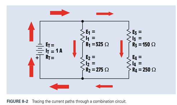
Refer to the circuit shown in Figure 8-2. Redraw the circuit and use the following values:
Assume that an ammeter indicates a total circuit current of 15 mA.
A voltmeter indicates the following voltage drops across each resistor:
What is the most likely problem with this circuit?

Trending nowThis is a popular solution!

Chapter 8 Solutions
Delmar's Standard Textbook Of Electricity


- When you connect a voltmeter to read a dc voltage a. polarity is not important b. connect the voltmeter in series with the circuit c. connect the voltmeter across the component d. connect the common meter lead to the most positive point in the circuitarrow_forwardTo measure current with an ammeter, connect the ammeter: A) across the load B) across the resistance C) across the voltage source D) in the current patharrow_forwardFigure 5 shows a current series feedback amplifier. The sampled current signal is the output current, I, flowing in resistor, Rg, where it develops a feedback signal voltage, V across the resistor, Rg. Determine: a) the feedback gain, B = I. 1. Io the gain without feedback, A = Vs b) A c) the gain with feedback, Af 1+BAarrow_forward
- A dc ammeter has an internal resistances of 0.1 ohm. A shunt of 1.010 milliohm is connected to the ammeter. What is the multiplier of the set-up?arrow_forwardDetermine the equivalent resistance of the Rab circuit 890 ohms 890 ohms 220 ohms a 470 ohms 100 ohms b 220 ohms 470 ohmsarrow_forward7. Determine all of the resistor values in figure below. if R₁ = 7730. +0 Vs 15.53 mA R₁ www 3.64 mA R₂ 6.67 mA R3 RA ww 3.08 mAarrow_forward
- Referring to the circuit below, an ammeter is connected in series with the 16-V source while a voltmeter is tapped across point C and the negative terminal of the source. Determine the reading on each of the instruments. Ammeter reading: Voltmeter reading:arrow_forwarda) Voltage at Node "A" in V is b) Current flowing through R5 in mA is c) Current flowing through R6 in mA is d) Current flowing through R7 in mA is e) Power dissipated by R8 in micro W isarrow_forwardWrite down the steps on how to Parallel Resistors Current Divisionarrow_forward
- Three circuits A, B and C are connected in series across a 200 V supply. The voltage across circuit A is 50 V, lagging the supply voltage by 45° and the voltage across circuit C is 100 V, leading the supply voltage by 30°. Determine the voltage across circuit B.arrow_forwardI am trying to establish the current in the 3 Ohm Resistor and the 24 Ohm Resistor as well as the potential difference between points A and B.arrow_forwardDraw the flow of current for the given circuit and discuss thouroughly how the three voltage drop are develop across each resistors. R1 R2 R3 Earrow_forward
 Delmar's Standard Textbook Of ElectricityElectrical EngineeringISBN:9781337900348Author:Stephen L. HermanPublisher:Cengage Learning
 Electricity for Refrigeration, Heating, and Air C...Mechanical EngineeringISBN:9781337399128Author:Russell E. SmithPublisher:Cengage Learning