
Concept explainers
Videos
Refer to the circuit shown in Figure 8-25 to solve the following problems.
Find the unknown values in the circuit if the total current is 0.8 A and the resistors have the following values:
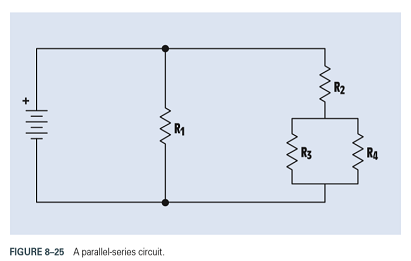
FIGURE 8-25 A parallel-series circuit.

Trending nowThis is a popular solution!

Chapter 8 Solutions
Delmar's Standard Textbook Of Electricity


- 1 8A 2)R1 and R2 using the source transformation method in the circuit on the left 20 R2 30 currents passing through resistors, voltages dissipated on resistors R1 and R2 V1 12 V 7A V1 and V2) are those.arrow_forwardEx8: Using the voltage divider rule, determine the voltages (V1 & V2) for the circuit shown below. (R1 60, R2 = 12N). E=+24V R1 Vi V2 R2 V2arrow_forwardDetermine the nodal voltages that are indicated in the circuit of the figurearrow_forward
- 3. Refer to the circuit shown in Figure 8-2. Redraw the circuit and use the following values: Assume that an ammeter indicates a total circuit current of 15 mA. A voltmeter indicates the following voltage drops across each resistor: What is the most likely problem with this circuit?arrow_forwardET E1 E2 E3 E41.248V IT I1 I2 I3 I4 RT R1 R2 R3 R4 PT0.576W P10.0806W P20.0461W P30.00184W P4 E5 E6 E7 E8 E9 I5 I6 I7 I8 I9 R5 R6 R7 R8 R9 P50.0203W P60.00995W P70.0518W P80.0726W P90.288W FIGURE 8-26 A combination circuit.arrow_forwardRefer to Figure 8-21. Assume that the resistors have the following values: R1=150R2=120R3=47R4=220 Assume that an ohmmeter connected across the entire circuit indicates a value of 245 . Does this reading indicate that there is a problem with the circuit and, if so, what is the most likely problem? FIGURE 8-21 Series-parallel circuit.arrow_forward
- Find the unknown values in the circuit if the applied voltage is 350 V and the resistors have the following values:arrow_forward3. Find the unknown values in the circuit if the applied voltage is 18 V and the resistors have the following values: FIGURE 8-21 Series-parallel circuit.arrow_forwardFind the missing values for the circuit shown in Figure 8-27. FIGURE 8-27 Combination circuit.arrow_forward
- Which statement is correct about a series circuit? The sum of currents in each load multiplied by the total resistance determines t voltage. The sum of the individual resistances equals the total resistance. The sum of all the voltage drops equals the source voltage. The voltage drops are equal to the input source. In a series circuit, the current, I, is Different in each resistor The highest near the positive and negative terminals of the voltage source The same everywhere Different at all points along the circuitarrow_forwardMULTIPLE CHOICE Question 8 A 22 V battery powers a parallel circuit. Each loop has a resistor that causes a 10 V potential difference. What is the voltage at the resistor located before the node? A 12 V B 32 V C 2.2 V D 220 Varrow_forwardSolve the following problem using Voltage Divider Rule. There is already an answer. Show your complete solutions. And write it on the paper.arrow_forward
 Delmar's Standard Textbook Of ElectricityElectrical EngineeringISBN:9781337900348Author:Stephen L. HermanPublisher:Cengage Learning