
Concept explainers
Videos
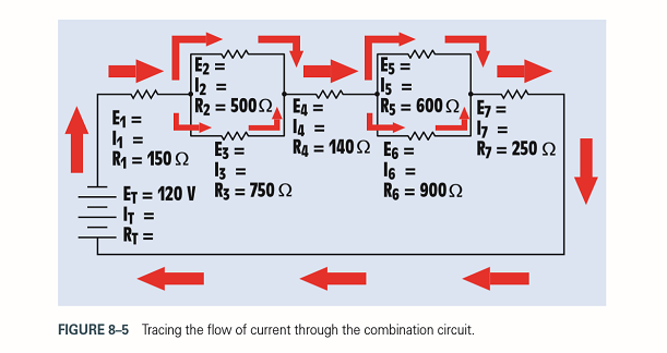
Refer to Figure 8-5. Replace the values shown with the following. Solve for all the unknown values.

Trending nowThis is a popular solution!

Chapter 8 Solutions
Delmar's Standard Textbook Of Electricity


- P3. Given the following network, determine: ⚫ 3.a. Equivalent Y ⚫ 3.b. Equivalent A 2 R[2] 10 8 b 20 30 5arrow_forward[Electrical Circuits] P1. Using the mesh current method, calculate the magnitude and direction of: 1.a. I and I (mesh currents) 1.b. I10 (test current in R10 = 1082) 1.c. (Calculate the magnitude and signs of V10) 6[A] 12 [√] بي 10 38 20 4A] Iw -800arrow_forwardNeed handwritten solution do not use chatgptarrow_forward
- [07/01, 16:59] C P: Question: Calculate the following for 100Hz and 500Hz (express all answers in phasor form). Show all work. A) Xc and ZTB) VR1 and VC1 C) IT Handwritten Solution Pleasearrow_forward1. Sketch the root loci of a system with the following characteristic equation: s²+2s+2+K(s+2)=0 2. Sketch the root loci for the following loop transfer function: KG(s)H(s)=- K(s+1) s(s+2)(s²+2s+4)arrow_forward3. For the unity feedback system with forward path transfer function, G(s), below: G(s)= K(s² +8) (s+4)(s+5) Sketch the root locus and show the breakaway/break-in point(s) and jo-axis crossing. Determine the angle of arrival and K value at the breakaway/break- in point(s). Give your comment the system is stable or unstable.arrow_forward
- Find the step response of each of the transfer functions shown in Eqs. (4.62) through (4.64) and compare them. [Shown in the image]Book: Norman S. Nise - Control Systems Engineering, 6th EditionTopic: Chapter-4: Time Response, Example 4.8Solve the math with proper explanation. Please don't give AI response. Asking for a expert verified answer.arrow_forward2. With respect to the circuit shown in Figure 2 below V2 -R1 R2 R4 w R3 R5 Figure 2: DC Circuit 2 a. Using Ohm's and Kirchhoff's laws calculate the current flowing through R3 and so determine wattage rating of R3. b. Verify your results with simulations. Note: you must use the values for the components in Table 2. Table 2 V2 (Volts) R1 (KQ) R2 (KQ) R3 (KQ) R4 (KQ) R5 (KQ) 9 3.3 5 10 6 1 3.3arrow_forwardDon't use ai to answer i will report your answerarrow_forward
- Don't use ai to answer I will report you answerarrow_forwardcircuit value of i1 and i2arrow_forwardIn the circuit shown in the figure, the switch opens at time t = 0. For t≥ 0 use I(t) and V₁(t) or Find Vc(t) and lc(t). D to icht) w 43 ViLC+) + vc(+) 5. F + 1252 18 A 3) 2H2VLCH 8 V 4л warrow_forward
 Delmar's Standard Textbook Of ElectricityElectrical EngineeringISBN:9781337900348Author:Stephen L. HermanPublisher:Cengage Learning