
Microelectronics: Circuit Analysis and Design
4th Edition
ISBN: 9780073380643
Author: Donald A. Neamen
Publisher: McGraw-Hill Companies, The
expand_more
expand_more
format_list_bulleted
Concept explainers
Videos
Textbook Question
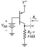
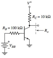
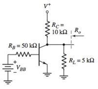
Chapter 6, Problem 6.8P
The parameters of each transistor in the circuits shown in Figure P6.8 are
Expert Solution & Answer
Want to see the full answer?
Check out a sample textbook solution
Students have asked these similar questions
Us
1. For the circuit in Figure 6.58, RE = 2 k, R1 = R2 = 50 k and the transistor parameters are ß =
100, VE B(on) = 0.7 V, and VA = 125 V. (a) Determine the small-signal voltage gain Av = vo/vs.
(b) Find the resistances Rib and Ro. (Ans. (a) Av = 0.925, (b) Rib = 4.37 k, Ro = 32.0)
3+1=
www
Vcc= +5 V
Rab 1
RE
Cc₂
IR₂
bot
Vo
R₁ =
500 £2
Figure 6.58 Figure for Exercises TYU 6.11.
Q6:A) A transistor dissipates 50W in an ambient temperature of 60°C.The thermal resistance are
exc-0.5
the junction temperature without a heat sink.
Determine the thermal resistance of the heat sink to avoid the junction exceeding 170°C.
°CW¹,0a-4°CW.Determine
5%
single polver supply
Solve for Collector Resistance (RC)
Chapter 6 Solutions
Microelectronics: Circuit Analysis and Design
Ch. 6 - The circuit parameters for the circuit in Figure...Ch. 6 - For the circuit in Figure 6.3, assume transistor...Ch. 6 - For the circuit in Figure 6.14(a), let =90 ,...Ch. 6 - Using the circuit and transistor parameters given...Ch. 6 - Consider the circuit in Figure 6.18. The circuit...Ch. 6 - Repeat Example 6.4 if the quiescent collector...Ch. 6 - For the circuit in Figure 6.31, let RE=0.6k ,...Ch. 6 - Prob. 6.6EPCh. 6 - The parameters of the circuit shown in Figure 6.28...Ch. 6 - For the circuit shown in Figure 6.31, let =100 ,...
Ch. 6 - Design the circuit in Figure 6.35 such that it is...Ch. 6 - For the circuit in Figure 6.28, the smallsignal...Ch. 6 - The circuit in Figure 6.38 has parameters V+=5V ,...Ch. 6 - For the circuit in Figure 6.39, let =125 ,...Ch. 6 - (a) Assume the circuit shown in Figure 6.40(a) is...Ch. 6 - For the circuit in Figure 6.39, let =125 ,...Ch. 6 - Reconsider the circuit in Figure 6.38. Let =120 ,...Ch. 6 - For the circuit shown in Figure 6.48, let =120 ,...Ch. 6 - For the circuit in Figure 6.31, use the parameters...Ch. 6 - Consider the circuit in Figure 6.38. Assume...Ch. 6 - For the circuit shown in Figure 6.49, let VCC=12V...Ch. 6 - Consider the circuit and transistor parameters...Ch. 6 - For the circuit in Figure 6.54, the transistor...Ch. 6 - Assume the circuit in Figure 6.57 uses a 2N2222...Ch. 6 - For the circuit in Figure 6.58, RE=2k , R1=R2=50k...Ch. 6 - Prob. 6.12TYUCh. 6 - For the circuit shown in Figure 6.63, the...Ch. 6 - Prob. 6.14TYUCh. 6 - For the circuit shown in Figure 6.64, let RS=0 ,...Ch. 6 - Consider the circuit in Figure 6.70(a). Let =100 ,...Ch. 6 - In the circuit in Figure 6.74 the transistor...Ch. 6 - Discuss, using the concept of a load line, how a...Ch. 6 - Prob. 2RQCh. 6 - Prob. 3RQCh. 6 - Sketch the hybrid- equivalent circuit of an npn...Ch. 6 - Prob. 5RQCh. 6 - Prob. 6RQCh. 6 - Prob. 7RQCh. 6 - Prob. 8RQCh. 6 - Prob. 9RQCh. 6 - Sketch a simple emitter-follower amplifier circuit...Ch. 6 - Sketch a simple common-base amplifier circuit and...Ch. 6 - Compare the ac circuit characteristics of the...Ch. 6 - Prob. 13RQCh. 6 - Prob. 14RQCh. 6 - (a) Determine the smallsignal parameters gm,r ,...Ch. 6 - (a) The transistor parameters are =125 and VA=200V...Ch. 6 - A transistor has a current gain in the range 90180...Ch. 6 - The transistor in Figure 6.3 has parameters =120...Ch. 6 - Prob. 6.5PCh. 6 - For the circuit in Figure 6.3, =120 , VCC=5V ,...Ch. 6 - The parameters of each transistor in the circuits...Ch. 6 - The parameters of each transistor in the circuits...Ch. 6 - The circuit in Figure 6.3 is biased at VCC=10V and...Ch. 6 - For the circuit in Figure 6.14, =100 , VA= ,...Ch. 6 - Prob. 6.11PCh. 6 - The parameters of the transistor in the circuit in...Ch. 6 - Assume that =100 , VA= , R1=33k , and R2=50k for...Ch. 6 - The transistor parameters for the circuit in...Ch. 6 - For the circuit in Figure P6.15, the transistor...Ch. 6 - Prob. D6.16PCh. 6 - The signal source in Figure P6.18 is s=5sintmV ....Ch. 6 - Consider the circuit shown in Figure P6.19 where...Ch. 6 - Prob. 6.20PCh. 6 - Figure P6.21 The parameters of the transistor in...Ch. 6 - Prob. 6.22PCh. 6 - For the circuit in Figure P6.23, the transistor...Ch. 6 - The transistor in the circuit in Figure P6.24 has...Ch. 6 - For the transistor in the circuit in Figure P6.26,...Ch. 6 - If the collector of a transistor is connected to...Ch. 6 - Consider the circuit shown in Figure P6.13. Assume...Ch. 6 - For the circuit in Figure P6.15, let =100 , VA= ,...Ch. 6 - Consider the circuit in Figure P6.19. The...Ch. 6 - The parameters of the circuit shown in Figure...Ch. 6 - Consider the circuit in Figure P6.26 with...Ch. 6 - For the circuit in Figure P6.20, the transistor...Ch. 6 - In the circuit in Figure P6.22 with transistor...Ch. 6 - For the circuit in Figure P6.24, the transistor...Ch. 6 - Prob. 6.40PCh. 6 - Consider the ac equivalent circuit in Figure...Ch. 6 - For the ac equivalent circuit in Figure P6.42,...Ch. 6 - The circuit and transistor parameters for the ac...Ch. 6 - Consider the circuit in Figure P6.45. The...Ch. 6 - For the transistor in Figure P6.47, =80 and...Ch. 6 - Consider the emitterfollower amplifier shown in...Ch. 6 - The transistor parameters for the circuit in...Ch. 6 - In the circuit shown in Figure P6.51, determine...Ch. 6 - The transistor current gain in the circuit shown...Ch. 6 - Consider the circuit shown in Figure P6.47. The...Ch. 6 - For the circuit in Figure P6.54, the parameters...Ch. 6 - Figure P6.59 is an ac equivalent circuit of a...Ch. 6 - The transistor in the ac equivalent circuit shown...Ch. 6 - Consider the ac equivalent commonbase circuit...Ch. 6 - Prob. 6.62PCh. 6 - The transistor in the circuit shown in Figure...Ch. 6 - Repeat Problem 6.63 with a 100 resistor in series...Ch. 6 - Consider the commonbase circuit in Figure P6.65....Ch. 6 - For the circuit shown in Figure P6.66, the...Ch. 6 - The parameters of the circuit in Figure P6.67 are...Ch. 6 - For the commonbase circuit shown in Figure P6.67,...Ch. 6 - Consider the circuit shown in Figure P6.69. The...Ch. 6 - In the circuit of Figure P6.71, let VEE=VCC=5V ,...Ch. 6 - Consider the ac equivalent circuit in Figure...Ch. 6 - The transistor parameters in the ac equivalent...Ch. 6 - Consider the circuit shown in Figure 6.38. The...Ch. 6 - For the circuit shown in Figure 6.57, the...
Knowledge Booster


Learn more about
Need a deep-dive on the concept behind this application? Look no further. Learn more about this topic, electrical-engineering and related others by exploring similar questions and additional content below.Similar questions
- 6.4) Explain conceptually whygm( sat) andgare the same. Where, g is conductance and gm(sat) is saturation transconductance.arrow_forward5- a-) Define the MOSFET in the figure, explain by drawing its input and output circuit characteristics.b-) Since k=0.1 mA/V2, VGS=5V and VT=2.5V for this MOSFET, find the VDS voltage using the circuit.arrow_forwardMOSFET Amplifier: 1. Determine the drain-to-source voltage (VDs) if VDD = +1sV and RD = 6202. The MOSFET data sheet gives and Ipss = 12 mA. (Ans: Vps=10.6 V) %3Darrow_forward
- If collector current Ic = 6mA, 60µA in a BJT, then emitter current IE and base current IR = %3D is equal to а. 6.6UA O b. 6.6mA C. 6.06mA d. 66HAarrow_forwardIn the circuit shown in Example 6.4 (Figure 6.42), assume that the values of Rg = 10 kn, Rc 100 92, VBB = 5 V, and Vcc = 10 V. Assume that the current gain is 100. Calculate the transistor currents and voltages across different junctions. VBB + HAND WRITTEN ONLY, RB IB Rc VcB_++ [/c VBE VCE E Vccarrow_forwardDraw zener regulator circuit to obtain regulated DC voltage 6.8v . considering input DC voltage in the range from 10v to 30v . consider load resistance of 10kohmarrow_forward
- 04:- Design a bias circuit for NPN silicon transistor having a nominal B-100 to be used in voltage divider circuit with Q-point of Ic 10 mA and VCE = 10 V. Use standard valued 5% resistors and draw a schematic diagram of your design. (10 points)arrow_forwardc) When considering thyristor switching why is Isolated Gate Control needed ? d) The filtered rectifier output is now feeds the regulator circuit shown in figure Q6b. i) Name the type of regulator shown in the shaded area and briefly describe its operation. ii) If the voltage, VL, that appears across the potential divider is regulated to 5V what size zener diode is used? The entire circuit uses the op-amp comparator to iii) allow the limit on the maximum load current to be varied. Explain the operation of the circuit and identify the maximum load current, IL , allowed if the potentiometer's output is 4V and Rx is 20 ?arrow_forward1. For a certain D-MOSFET, IDSS = 18 mA, and VGS = +10V. Vp =4V. a) Determine ID at VGS =+ 3V. b) Determine ID at VGS = -3V. %3Darrow_forward
- Ideally, a dc load line is a straight line drawn on the collector characteristic curves between VCE(cutoff) and /C(sat) the Q-point and cutoff the Q-point and saturation IB = 0 and IB = IC / Bdcarrow_forwardFor positive half of the signal below, what is the peak output value of the circuit? NOTE: use silicon diode ?arrow_forwardQUESTION 4 In this voltage divider bias circuit, the input is at the base. Output is at the emitter with a high input resistance and low output resistance. The maximum voltage gain is 1 and the coupling capacitors must have a negligible reactance at the frequency of operation. (use to answer a and b) a. Derive the expression for the voltage gain, current gain, and power gain in terms of power delivered to the load, RL. b. Sketch both the DC and AC equivalent circuits. c. Derive the expression for ripple factor of Half Wave Rectification with a capacitor filter.arrow_forward
arrow_back_ios
SEE MORE QUESTIONS
arrow_forward_ios
Recommended textbooks for you
 Introductory Circuit Analysis (13th Edition)Electrical EngineeringISBN:9780133923605Author:Robert L. BoylestadPublisher:PEARSON
 Delmar's Standard Textbook Of ElectricityElectrical EngineeringISBN:9781337900348Author:Stephen L. HermanPublisher:Cengage Learning
 Programmable Logic ControllersElectrical EngineeringISBN:9780073373843Author:Frank D. PetruzellaPublisher:McGraw-Hill Education
 Fundamentals of Electric CircuitsElectrical EngineeringISBN:9780078028229Author:Charles K Alexander, Matthew SadikuPublisher:McGraw-Hill Education
 Electric Circuits. (11th Edition)Electrical EngineeringISBN:9780134746968Author:James W. Nilsson, Susan RiedelPublisher:PEARSON
 Engineering ElectromagneticsElectrical EngineeringISBN:9780078028151Author:Hayt, William H. (william Hart), Jr, BUCK, John A.Publisher:Mcgraw-hill Education,
Introductory Circuit Analysis (13th Edition)
Electrical Engineering
ISBN:9780133923605
Author:Robert L. Boylestad
Publisher:PEARSON
Delmar's Standard Textbook Of Electricity
Electrical Engineering
ISBN:9781337900348
Author:Stephen L. Herman
Publisher:Cengage Learning
Programmable Logic Controllers
Electrical Engineering
ISBN:9780073373843
Author:Frank D. Petruzella
Publisher:McGraw-Hill Education
Fundamentals of Electric Circuits
Electrical Engineering
ISBN:9780078028229
Author:Charles K Alexander, Matthew Sadiku
Publisher:McGraw-Hill Education
Electric Circuits. (11th Edition)
Electrical Engineering
ISBN:9780134746968
Author:James W. Nilsson, Susan Riedel
Publisher:PEARSON
Engineering Electromagnetics
Electrical Engineering
ISBN:9780078028151
Author:Hayt, William H. (william Hart), Jr, BUCK, John A.
Publisher:Mcgraw-hill Education,
How does an Antenna work? | ICT #4; Author: Lesics;https://www.youtube.com/watch?v=ZaXm6wau-jc;License: Standard Youtube License