
(a)
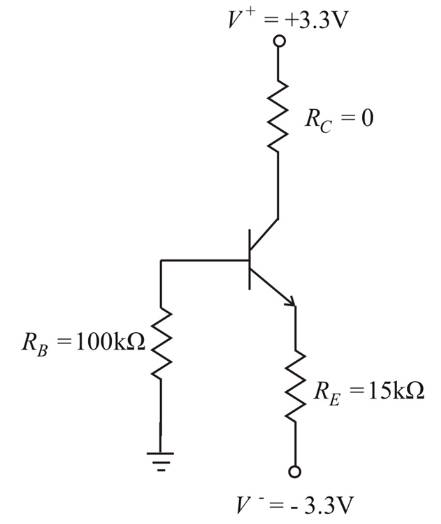
The quiescent values
(a)
Answer to Problem 6.12TYU
The values are
Explanation of Solution
Given:
Given circuit:
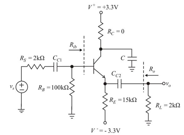
Given Data:
Calculation:
Considering the BJT (Bipolar Junction Transistor) as single node, then, by Kirchhoff's current law, the quiescent emitter current
In CE mode:
The quiescent collector current
Here,
From equations (1) and (2),
(Reducing the ac source
Using equation (3),
From equation (3),
Using equation (4),
Applying Kirchhoff’s voltage law around the collector-emitter loop as,
From equation (2),
Using the equation (4),
(b)
The small-signal voltage gain and small-signal current gain
(b)
Answer to Problem 6.12TYU
The values of small signal voltage and small signal current gain are:
Explanation of Solution
Given:
Given circuit:

Given Data:
Calculation:
Small-signal analysis of given circuit:
[Reducing the dc source to zero and shorting all capacitors]

Determining the Diffusion resistance
Using equation (6),
Let
The input resistance
Using equations (7) and
Let
Using the equation (9),
Finding the Small signal voltage gain
Using equations (7) and
Finding the Small signal current gain
Using equation (9),
(c)
The small-signal input resistance
(c)
Answer to Problem 6.12TYU
The values of small-signal input resistance
Explanation of Solution
Given:
Given circuit:

Given Data:
Calculation:
Small-signal analysis of given circuit:
[Reducing the dc source to zero and shorting all capacitors]
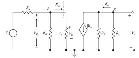
Determining the Diffusion resistance
Using the equation (6),
Let
The input resistance
Using the equations (7) and
Determining the input resistance
From the equation (9), we get
The output resistance
Using the equation (7),
Want to see more full solutions like this?
Chapter 6 Solutions
Microelectronics: Circuit Analysis and Design

- Design a circuit using a 200k Ohm potentiometer that has a output voltage, Vout, that ranges from a minimum of 1/3Vs volts to Vs volts.arrow_forwardDesign a circuit that amplifies a 500 mV signal originating from a computer keyboard, so that this signal can be interpreted by the digital circuits found on the motherboard.arrow_forwardDerive an expression for the output voltage of the circuit in Fig. 6.22 in terms of the four input voltages. Simplify your result as much as possible.arrow_forward
- The system of using helicopters to work on live power lines is based on the principle that electrical current seeks to flow into the ground. Select one: True Falsearrow_forwardIf in the circuit of Example 5.5 the value of R, is doubled (to 13.1 k52), find approximate values for I, and V» Ans. 0.15 mA: 0.05 V Need workarrow_forwardSolve for the parameter being asked in the given circuits using the stated circuit analysis methods.arrow_forward
- A transformer-coupled (3:1) class A amplifier supplies its output power at an RL of 10 ohms, if the maximum AC output power is 2 watts, calculate the collector currentarrow_forward4b. i. Expand on the instance at which the transmitter assumes a more active role in synchronization. Give an example. (ii). Per the knowledge gained in Ait as communication student convince a team of engineers who wants to install a network but have a challenge as to what system to use in terms of technology, whether analog or digital. Your submission should not be less than two pages.arrow_forward10. An equivalent model is a combination of appropriately selected circuit elements that accurately simulates the real behavior of a semiconductor device in any operating condition. Select one: TrueFalsearrow_forward
- What is the voltage gain of the instrumentation amplifier as shown if R1 = 1.5 kΩ, R2 = 75 kΩ, R3 = 10 kΩ, and R4 = 10 kΩ. What is the outputvoltage if υ1 = (2 + 0.1 sin 2000πt) V and υ2 = 2.1 V?arrow_forwardIn a city in England with a temperature of 18 ° C, it is desired to install a wind farm with 10 wind turbines 80m high and aerodynamic coefficient equal to 0.3. For this, a study of wind measurement through an anemometer installed at 15 m height indicating speed 5 m / s in a place with high grass. Size the turbine blades in this wind farm so that obtain a mechanical power of 500 kW that will supply the entire community, calculating the diameter of the rotor blades.arrow_forwardevaluate the circuitarrow_forward
 Introductory Circuit Analysis (13th Edition)Electrical EngineeringISBN:9780133923605Author:Robert L. BoylestadPublisher:PEARSON
 Delmar's Standard Textbook Of ElectricityElectrical EngineeringISBN:9781337900348Author:Stephen L. HermanPublisher:Cengage Learning
 Programmable Logic ControllersElectrical EngineeringISBN:9780073373843Author:Frank D. PetruzellaPublisher:McGraw-Hill Education
 Fundamentals of Electric CircuitsElectrical EngineeringISBN:9780078028229Author:Charles K Alexander, Matthew SadikuPublisher:McGraw-Hill Education
 Electric Circuits. (11th Edition)Electrical EngineeringISBN:9780134746968Author:James W. Nilsson, Susan RiedelPublisher:PEARSON
 Engineering ElectromagneticsElectrical EngineeringISBN:9780078028151Author:Hayt, William H. (william Hart), Jr, BUCK, John A.Publisher:Mcgraw-hill Education,