
Microelectronics: Circuit Analysis and Design
4th Edition
ISBN: 9780073380643
Author: Donald A. Neamen
Publisher: McGraw-Hill Companies, The
expand_more
expand_more
format_list_bulleted
Videos
Textbook Question
Chapter 6, Problem 6.68P
For the common−base circuit shown in Figure P6.67, let
 and
and The transistor parameters are
 and
and (a) Design the circuit such that the minimum small−signal voltage gain is
 (b) What are the Q−point values? (c) Determine the small−signal voltage gain if
 is bypassed by a large capacitor.
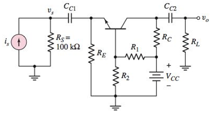
Figure P6.67
Expert Solution & Answer
Want to see the full answer?
Check out a sample textbook solution
Students have asked these similar questions
All field-effect transistors are unipolar
rather than bipolar devices. That is, the main
current through them is comprised either of
through an N-type semiconductor *
..... .....
This is about Bipolar Junction Transistors:
Discuss collector characteristic curves and identify and explain the different regions.
Draw zener regulator circuit to obtain regulated DC voltage 6.8v . considering input DC voltage in the range from 10v to 30v . consider load resistance of 10kohm
Chapter 6 Solutions
Microelectronics: Circuit Analysis and Design
Ch. 6 - The circuit parameters for the circuit in Figure...Ch. 6 - For the circuit in Figure 6.3, assume transistor...Ch. 6 - For the circuit in Figure 6.14(a), let =90 ,...Ch. 6 - Using the circuit and transistor parameters given...Ch. 6 - Consider the circuit in Figure 6.18. The circuit...Ch. 6 - Repeat Example 6.4 if the quiescent collector...Ch. 6 - For the circuit in Figure 6.31, let RE=0.6k ,...Ch. 6 - Prob. 6.6EPCh. 6 - The parameters of the circuit shown in Figure 6.28...Ch. 6 - For the circuit shown in Figure 6.31, let =100 ,...
Ch. 6 - Design the circuit in Figure 6.35 such that it is...Ch. 6 - For the circuit in Figure 6.28, the smallsignal...Ch. 6 - The circuit in Figure 6.38 has parameters V+=5V ,...Ch. 6 - For the circuit in Figure 6.39, let =125 ,...Ch. 6 - (a) Assume the circuit shown in Figure 6.40(a) is...Ch. 6 - For the circuit in Figure 6.39, let =125 ,...Ch. 6 - Reconsider the circuit in Figure 6.38. Let =120 ,...Ch. 6 - For the circuit shown in Figure 6.48, let =120 ,...Ch. 6 - For the circuit in Figure 6.31, use the parameters...Ch. 6 - Consider the circuit in Figure 6.38. Assume...Ch. 6 - For the circuit shown in Figure 6.49, let VCC=12V...Ch. 6 - Consider the circuit and transistor parameters...Ch. 6 - For the circuit in Figure 6.54, the transistor...Ch. 6 - Assume the circuit in Figure 6.57 uses a 2N2222...Ch. 6 - For the circuit in Figure 6.58, RE=2k , R1=R2=50k...Ch. 6 - Prob. 6.12TYUCh. 6 - For the circuit shown in Figure 6.63, the...Ch. 6 - Prob. 6.14TYUCh. 6 - For the circuit shown in Figure 6.64, let RS=0 ,...Ch. 6 - Consider the circuit in Figure 6.70(a). Let =100 ,...Ch. 6 - In the circuit in Figure 6.74 the transistor...Ch. 6 - Discuss, using the concept of a load line, how a...Ch. 6 - Prob. 2RQCh. 6 - Prob. 3RQCh. 6 - Sketch the hybrid- equivalent circuit of an npn...Ch. 6 - Prob. 5RQCh. 6 - Prob. 6RQCh. 6 - Prob. 7RQCh. 6 - Prob. 8RQCh. 6 - Prob. 9RQCh. 6 - Sketch a simple emitter-follower amplifier circuit...Ch. 6 - Sketch a simple common-base amplifier circuit and...Ch. 6 - Compare the ac circuit characteristics of the...Ch. 6 - Prob. 13RQCh. 6 - Prob. 14RQCh. 6 - (a) Determine the smallsignal parameters gm,r ,...Ch. 6 - (a) The transistor parameters are =125 and VA=200V...Ch. 6 - A transistor has a current gain in the range 90180...Ch. 6 - The transistor in Figure 6.3 has parameters =120...Ch. 6 - Prob. 6.5PCh. 6 - For the circuit in Figure 6.3, =120 , VCC=5V ,...Ch. 6 - The parameters of each transistor in the circuits...Ch. 6 - The parameters of each transistor in the circuits...Ch. 6 - The circuit in Figure 6.3 is biased at VCC=10V and...Ch. 6 - For the circuit in Figure 6.14, =100 , VA= ,...Ch. 6 - Prob. 6.11PCh. 6 - The parameters of the transistor in the circuit in...Ch. 6 - Assume that =100 , VA= , R1=33k , and R2=50k for...Ch. 6 - The transistor parameters for the circuit in...Ch. 6 - For the circuit in Figure P6.15, the transistor...Ch. 6 - Prob. D6.16PCh. 6 - The signal source in Figure P6.18 is s=5sintmV ....Ch. 6 - Consider the circuit shown in Figure P6.19 where...Ch. 6 - Prob. 6.20PCh. 6 - Figure P6.21 The parameters of the transistor in...Ch. 6 - Prob. 6.22PCh. 6 - For the circuit in Figure P6.23, the transistor...Ch. 6 - The transistor in the circuit in Figure P6.24 has...Ch. 6 - For the transistor in the circuit in Figure P6.26,...Ch. 6 - If the collector of a transistor is connected to...Ch. 6 - Consider the circuit shown in Figure P6.13. Assume...Ch. 6 - For the circuit in Figure P6.15, let =100 , VA= ,...Ch. 6 - Consider the circuit in Figure P6.19. The...Ch. 6 - The parameters of the circuit shown in Figure...Ch. 6 - Consider the circuit in Figure P6.26 with...Ch. 6 - For the circuit in Figure P6.20, the transistor...Ch. 6 - In the circuit in Figure P6.22 with transistor...Ch. 6 - For the circuit in Figure P6.24, the transistor...Ch. 6 - Prob. 6.40PCh. 6 - Consider the ac equivalent circuit in Figure...Ch. 6 - For the ac equivalent circuit in Figure P6.42,...Ch. 6 - The circuit and transistor parameters for the ac...Ch. 6 - Consider the circuit in Figure P6.45. The...Ch. 6 - For the transistor in Figure P6.47, =80 and...Ch. 6 - Consider the emitterfollower amplifier shown in...Ch. 6 - The transistor parameters for the circuit in...Ch. 6 - In the circuit shown in Figure P6.51, determine...Ch. 6 - The transistor current gain in the circuit shown...Ch. 6 - Consider the circuit shown in Figure P6.47. The...Ch. 6 - For the circuit in Figure P6.54, the parameters...Ch. 6 - Figure P6.59 is an ac equivalent circuit of a...Ch. 6 - The transistor in the ac equivalent circuit shown...Ch. 6 - Consider the ac equivalent commonbase circuit...Ch. 6 - Prob. 6.62PCh. 6 - The transistor in the circuit shown in Figure...Ch. 6 - Repeat Problem 6.63 with a 100 resistor in series...Ch. 6 - Consider the commonbase circuit in Figure P6.65....Ch. 6 - For the circuit shown in Figure P6.66, the...Ch. 6 - The parameters of the circuit in Figure P6.67 are...Ch. 6 - For the commonbase circuit shown in Figure P6.67,...Ch. 6 - Consider the circuit shown in Figure P6.69. The...Ch. 6 - In the circuit of Figure P6.71, let VEE=VCC=5V ,...Ch. 6 - Consider the ac equivalent circuit in Figure...Ch. 6 - The transistor parameters in the ac equivalent...Ch. 6 - Consider the circuit shown in Figure 6.38. The...Ch. 6 - For the circuit shown in Figure 6.57, the...
Knowledge Booster


Learn more about
Need a deep-dive on the concept behind this application? Look no further. Learn more about this topic, electrical-engineering and related others by exploring similar questions and additional content below.Similar questions
- Q6) d) Show by means of a diagram how you will normally connect external batteries ini. PNP transistorii. NPN transistore) Describe how a semiconductor will behave at absolute zero temperature.arrow_forwardDraw the equivalent Small signal Model and write an equation of Ro .arrow_forwardFor positive half of the signal below, what is the peak output value of the circuit? NOTE: use silicon diode ?arrow_forward
- draw the following systems: 1- AM generation -Square law product. 2- PM generation- frequency modulator.arrow_forward5- a-) Define the MOSFET in the figure, explain by drawing its input and output circuit characteristics.b-) Since k=0.1 mA/V2, VGS=5V and VT=2.5V for this MOSFET, find the VDS voltage using the circuit.arrow_forwardDiscuss the significant different between the construction of an E-MOSFET and a D-MOSFET.arrow_forward
- With Neat sketch explain the construction, operation, VI characteristics, application and features of the power semiconductor device which is having low on state loss and small switching frequency operationarrow_forwardGiven the figure below, sketch the spectrum for the half-wave rectified signal showing harmonics up to the 5th. Also show the voltage and frequency scale and indicate the voltage scale in peak voltage.arrow_forwardTransform and draw the equivalent small signal circuit model using ONLY theHYBRID-PI model.arrow_forward
- What are the transistor fabrication techniques, process of fabrication, structure.arrow_forwardUs 1. For the circuit in Figure 6.58, RE = 2 k, R1 = R2 = 50 k and the transistor parameters are ß = 100, VE B(on) = 0.7 V, and VA = 125 V. (a) Determine the small-signal voltage gain Av = vo/vs. (b) Find the resistances Rib and Ro. (Ans. (a) Av = 0.925, (b) Rib = 4.37 k, Ro = 32.0) 3+1= www Vcc= +5 V Rab 1 RE Cc₂ IR₂ bot Vo R₁ = 500 £2 Figure 6.58 Figure for Exercises TYU 6.11.arrow_forwardC-A transistor supplies 2W to 4k2 load. The zero signal collector current is 35mA and the D.C. collector current with signal is 39mA. Determine the second order harmonic distortion.arrow_forward
arrow_back_ios
SEE MORE QUESTIONS
arrow_forward_ios
Recommended textbooks for you
 Introductory Circuit Analysis (13th Edition)Electrical EngineeringISBN:9780133923605Author:Robert L. BoylestadPublisher:PEARSON
 Delmar's Standard Textbook Of ElectricityElectrical EngineeringISBN:9781337900348Author:Stephen L. HermanPublisher:Cengage Learning
 Programmable Logic ControllersElectrical EngineeringISBN:9780073373843Author:Frank D. PetruzellaPublisher:McGraw-Hill Education
 Fundamentals of Electric CircuitsElectrical EngineeringISBN:9780078028229Author:Charles K Alexander, Matthew SadikuPublisher:McGraw-Hill Education
 Electric Circuits. (11th Edition)Electrical EngineeringISBN:9780134746968Author:James W. Nilsson, Susan RiedelPublisher:PEARSON
 Engineering ElectromagneticsElectrical EngineeringISBN:9780078028151Author:Hayt, William H. (william Hart), Jr, BUCK, John A.Publisher:Mcgraw-hill Education,
Introductory Circuit Analysis (13th Edition)
Electrical Engineering
ISBN:9780133923605
Author:Robert L. Boylestad
Publisher:PEARSON
Delmar's Standard Textbook Of Electricity
Electrical Engineering
ISBN:9781337900348
Author:Stephen L. Herman
Publisher:Cengage Learning
Programmable Logic Controllers
Electrical Engineering
ISBN:9780073373843
Author:Frank D. Petruzella
Publisher:McGraw-Hill Education
Fundamentals of Electric Circuits
Electrical Engineering
ISBN:9780078028229
Author:Charles K Alexander, Matthew Sadiku
Publisher:McGraw-Hill Education
Electric Circuits. (11th Edition)
Electrical Engineering
ISBN:9780134746968
Author:James W. Nilsson, Susan Riedel
Publisher:PEARSON
Engineering Electromagnetics
Electrical Engineering
ISBN:9780078028151
Author:Hayt, William H. (william Hart), Jr, BUCK, John A.
Publisher:Mcgraw-hill Education,
02 - Sinusoidal AC Voltage Sources in Circuits, Part 1; Author: Math and Science;https://www.youtube.com/watch?v=8zMiIHVMfaw;License: Standard Youtube License