
Microelectronics: Circuit Analysis and Design
4th Edition
ISBN: 9780073380643
Author: Donald A. Neamen
Publisher: McGraw-Hill Companies, The
expand_more
expand_more
format_list_bulleted
Concept explainers
Videos
Textbook Question
Chapter 6, Problem 6.69P
Consider the circuit shown in Figure P6.69. The transistor has parameters
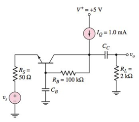
Figure P6.69
Expert Solution & Answer
Want to see the full answer?
Check out a sample textbook solution
Students have asked these similar questions
Define the region of operation for the JFET of figure 6.57 if VDSmax= 25 V and PDmax= 120 mW.
6.13 Obtain the model of the voltage vo, given the supply voltage v,, for the circuit
shown in Figure P6.13.
Figure P6.13
Vo
The transistor in the circuit shown in Figure P6.58 has
B = 100 and VA = 0. (a) Determine the quiescent
values IC Q and VEC Q. (b) Determine the small-signal
voltage gain Av = vo/vs.
Figure p6.58
Rg=
10 k2
Rc3=
5 k2
50 k2
v* = +10 V
V-=-10 V
Figure P6.58
Chapter 6 Solutions
Microelectronics: Circuit Analysis and Design
Ch. 6 - The circuit parameters for the circuit in Figure...Ch. 6 - For the circuit in Figure 6.3, assume transistor...Ch. 6 - For the circuit in Figure 6.14(a), let =90 ,...Ch. 6 - Using the circuit and transistor parameters given...Ch. 6 - Consider the circuit in Figure 6.18. The circuit...Ch. 6 - Repeat Example 6.4 if the quiescent collector...Ch. 6 - For the circuit in Figure 6.31, let RE=0.6k ,...Ch. 6 - Prob. 6.6EPCh. 6 - The parameters of the circuit shown in Figure 6.28...Ch. 6 - For the circuit shown in Figure 6.31, let =100 ,...
Ch. 6 - Design the circuit in Figure 6.35 such that it is...Ch. 6 - For the circuit in Figure 6.28, the smallsignal...Ch. 6 - The circuit in Figure 6.38 has parameters V+=5V ,...Ch. 6 - For the circuit in Figure 6.39, let =125 ,...Ch. 6 - (a) Assume the circuit shown in Figure 6.40(a) is...Ch. 6 - For the circuit in Figure 6.39, let =125 ,...Ch. 6 - Reconsider the circuit in Figure 6.38. Let =120 ,...Ch. 6 - For the circuit shown in Figure 6.48, let =120 ,...Ch. 6 - For the circuit in Figure 6.31, use the parameters...Ch. 6 - Consider the circuit in Figure 6.38. Assume...Ch. 6 - For the circuit shown in Figure 6.49, let VCC=12V...Ch. 6 - Consider the circuit and transistor parameters...Ch. 6 - For the circuit in Figure 6.54, the transistor...Ch. 6 - Assume the circuit in Figure 6.57 uses a 2N2222...Ch. 6 - For the circuit in Figure 6.58, RE=2k , R1=R2=50k...Ch. 6 - Prob. 6.12TYUCh. 6 - For the circuit shown in Figure 6.63, the...Ch. 6 - Prob. 6.14TYUCh. 6 - For the circuit shown in Figure 6.64, let RS=0 ,...Ch. 6 - Consider the circuit in Figure 6.70(a). Let =100 ,...Ch. 6 - In the circuit in Figure 6.74 the transistor...Ch. 6 - Discuss, using the concept of a load line, how a...Ch. 6 - Prob. 2RQCh. 6 - Prob. 3RQCh. 6 - Sketch the hybrid- equivalent circuit of an npn...Ch. 6 - Prob. 5RQCh. 6 - Prob. 6RQCh. 6 - Prob. 7RQCh. 6 - Prob. 8RQCh. 6 - Prob. 9RQCh. 6 - Sketch a simple emitter-follower amplifier circuit...Ch. 6 - Sketch a simple common-base amplifier circuit and...Ch. 6 - Compare the ac circuit characteristics of the...Ch. 6 - Prob. 13RQCh. 6 - Prob. 14RQCh. 6 - (a) Determine the smallsignal parameters gm,r ,...Ch. 6 - (a) The transistor parameters are =125 and VA=200V...Ch. 6 - A transistor has a current gain in the range 90180...Ch. 6 - The transistor in Figure 6.3 has parameters =120...Ch. 6 - Prob. 6.5PCh. 6 - For the circuit in Figure 6.3, =120 , VCC=5V ,...Ch. 6 - The parameters of each transistor in the circuits...Ch. 6 - The parameters of each transistor in the circuits...Ch. 6 - The circuit in Figure 6.3 is biased at VCC=10V and...Ch. 6 - For the circuit in Figure 6.14, =100 , VA= ,...Ch. 6 - Prob. 6.11PCh. 6 - The parameters of the transistor in the circuit in...Ch. 6 - Assume that =100 , VA= , R1=33k , and R2=50k for...Ch. 6 - The transistor parameters for the circuit in...Ch. 6 - For the circuit in Figure P6.15, the transistor...Ch. 6 - Prob. D6.16PCh. 6 - The signal source in Figure P6.18 is s=5sintmV ....Ch. 6 - Consider the circuit shown in Figure P6.19 where...Ch. 6 - Prob. 6.20PCh. 6 - Figure P6.21 The parameters of the transistor in...Ch. 6 - Prob. 6.22PCh. 6 - For the circuit in Figure P6.23, the transistor...Ch. 6 - The transistor in the circuit in Figure P6.24 has...Ch. 6 - For the transistor in the circuit in Figure P6.26,...Ch. 6 - If the collector of a transistor is connected to...Ch. 6 - Consider the circuit shown in Figure P6.13. Assume...Ch. 6 - For the circuit in Figure P6.15, let =100 , VA= ,...Ch. 6 - Consider the circuit in Figure P6.19. The...Ch. 6 - The parameters of the circuit shown in Figure...Ch. 6 - Consider the circuit in Figure P6.26 with...Ch. 6 - For the circuit in Figure P6.20, the transistor...Ch. 6 - In the circuit in Figure P6.22 with transistor...Ch. 6 - For the circuit in Figure P6.24, the transistor...Ch. 6 - Prob. 6.40PCh. 6 - Consider the ac equivalent circuit in Figure...Ch. 6 - For the ac equivalent circuit in Figure P6.42,...Ch. 6 - The circuit and transistor parameters for the ac...Ch. 6 - Consider the circuit in Figure P6.45. The...Ch. 6 - For the transistor in Figure P6.47, =80 and...Ch. 6 - Consider the emitterfollower amplifier shown in...Ch. 6 - The transistor parameters for the circuit in...Ch. 6 - In the circuit shown in Figure P6.51, determine...Ch. 6 - The transistor current gain in the circuit shown...Ch. 6 - Consider the circuit shown in Figure P6.47. The...Ch. 6 - For the circuit in Figure P6.54, the parameters...Ch. 6 - Figure P6.59 is an ac equivalent circuit of a...Ch. 6 - The transistor in the ac equivalent circuit shown...Ch. 6 - Consider the ac equivalent commonbase circuit...Ch. 6 - Prob. 6.62PCh. 6 - The transistor in the circuit shown in Figure...Ch. 6 - Repeat Problem 6.63 with a 100 resistor in series...Ch. 6 - Consider the commonbase circuit in Figure P6.65....Ch. 6 - For the circuit shown in Figure P6.66, the...Ch. 6 - The parameters of the circuit in Figure P6.67 are...Ch. 6 - For the commonbase circuit shown in Figure P6.67,...Ch. 6 - Consider the circuit shown in Figure P6.69. The...Ch. 6 - In the circuit of Figure P6.71, let VEE=VCC=5V ,...Ch. 6 - Consider the ac equivalent circuit in Figure...Ch. 6 - The transistor parameters in the ac equivalent...Ch. 6 - Consider the circuit shown in Figure 6.38. The...Ch. 6 - For the circuit shown in Figure 6.57, the...
Knowledge Booster


Learn more about
Need a deep-dive on the concept behind this application? Look no further. Learn more about this topic, electrical-engineering and related others by exploring similar questions and additional content below.Similar questions
- 1. Attenuator of -10dB has gain () 2. An output signal has a fundamental amplitude of 2.5V, second harmonic amplitude of 0.25V, and third harmonic amplitude of 0.1V. then the total harmonic distortion is found to be 3. The current capability of power diodes can be increased by placing two or more in 4. As the illumination on a photoconductive cell (photoresistive device) increases in intensity, the terminal resistance will 5. The LCD has the advantage of having than LED. 6. The triac is fundamentally a diac with a for controlling the turn-on condition. prevo t hat ltarrow_forward6.9. Write the equations that describe the input-output relationships for Figure P.6.9. U, G H, Н, Y, Figure P.6.9arrow_forwardHow it is generated Single Sideband Modulator Using Phasing Methoarrow_forward
- drive a formula for (SNR) of sinusoidal signal has been sampled and quantized.arrow_forward(a) Plot the even and odd parts of the signal of Figurearrow_forward1. For the following circuit assume re = 30.6 1 a. Draw the small signal equivalent circuit. b. Find the input impedance. c. Find output impedance. d. Find the voltage gain. e. Find the current gain. 4.72 10Farrow_forward
- Convert the Mealy state diagram to a Moore state diagram.arrow_forwardd) A regulator as shown in Figure 4 has an input voltage, Vs 12 V. The duty cycle, k = 0.35 and the switching frequency is 30 kHz. It also has an inductance, L= 200 µH, filter capacitance, C = 440 µF. The average load current, la = 1.25 A. Determine the; i. average output voltage, Va. ii. peak-to-peak output ripple voltage, AVc. iii. peak-to-peak output ripple current of inductor, AI. iv. peak current of the transistor, Ip. v. critical values of L and C. vi. critical values of L and C if Vs is increased to 14 V. Estimate the change in percentage for the critical values of L and C. V, Load V V G Figure 4arrow_forwardDraw the signal after adding -2.5 DC level with the given signal, sketch the new output signal and draw the required circuit and briefly specify the function of the circuit also name this phenomenon. 10arrow_forward
- Solve for the following (MOSFETs)arrow_forwardCoonsider the common emitter amplifier shown in figure below. Assume a β of 100, VBE = 0.7V, VT = 25mA and VA = 100V. Draw an equivalent DC model and determine the rπ, transconductance (gm) and ro. Draw an equaivalent AC model using the small-signal model Find an expression for vbe and vo in terms of the input voltagearrow_forwardQ6:A) A transistor dissipates 50W in an ambient temperature of 60°C.The thermal resistance are exc-0.5 the junction temperature without a heat sink. Determine the thermal resistance of the heat sink to avoid the junction exceeding 170°C. °CW¹,0a-4°CW.Determine 5% single polver supplyarrow_forward
arrow_back_ios
SEE MORE QUESTIONS
arrow_forward_ios
Recommended textbooks for you
 Introductory Circuit Analysis (13th Edition)Electrical EngineeringISBN:9780133923605Author:Robert L. BoylestadPublisher:PEARSON
 Delmar's Standard Textbook Of ElectricityElectrical EngineeringISBN:9781337900348Author:Stephen L. HermanPublisher:Cengage Learning
 Programmable Logic ControllersElectrical EngineeringISBN:9780073373843Author:Frank D. PetruzellaPublisher:McGraw-Hill Education
 Fundamentals of Electric CircuitsElectrical EngineeringISBN:9780078028229Author:Charles K Alexander, Matthew SadikuPublisher:McGraw-Hill Education
 Electric Circuits. (11th Edition)Electrical EngineeringISBN:9780134746968Author:James W. Nilsson, Susan RiedelPublisher:PEARSON
 Engineering ElectromagneticsElectrical EngineeringISBN:9780078028151Author:Hayt, William H. (william Hart), Jr, BUCK, John A.Publisher:Mcgraw-hill Education,
Introductory Circuit Analysis (13th Edition)
Electrical Engineering
ISBN:9780133923605
Author:Robert L. Boylestad
Publisher:PEARSON
Delmar's Standard Textbook Of Electricity
Electrical Engineering
ISBN:9781337900348
Author:Stephen L. Herman
Publisher:Cengage Learning
Programmable Logic Controllers
Electrical Engineering
ISBN:9780073373843
Author:Frank D. Petruzella
Publisher:McGraw-Hill Education
Fundamentals of Electric Circuits
Electrical Engineering
ISBN:9780078028229
Author:Charles K Alexander, Matthew Sadiku
Publisher:McGraw-Hill Education
Electric Circuits. (11th Edition)
Electrical Engineering
ISBN:9780134746968
Author:James W. Nilsson, Susan Riedel
Publisher:PEARSON
Engineering Electromagnetics
Electrical Engineering
ISBN:9780078028151
Author:Hayt, William H. (william Hart), Jr, BUCK, John A.
Publisher:Mcgraw-hill Education,
How does an Antenna work? | ICT #4; Author: Lesics;https://www.youtube.com/watch?v=ZaXm6wau-jc;License: Standard Youtube License