
Fundamentals of Electromagnetics with Engineering Applications
1st Edition
ISBN: 9780470105757
Author: Stuart M. Wentworth
Publisher: Wiley, John & Sons, Incorporated
expand_more
expand_more
format_list_bulleted
Concept explainers
Videos
Textbook Question
Chapter 6, Problem 6.47P
The top-down view of a microstrip circuit is shown in Figure 6.54. If the microstrip is supported by a 40-mil-thick alumina substrate, (a) determine the line width required to achieve a
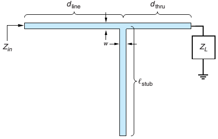
Figure 6.54 The top-down view of an open-ended microstrip stub-matching circuit for Problems 6.47 and 6.48.
Expert Solution & Answer
Want to see the full answer?
Check out a sample textbook solution
Students have asked these similar questions
Could you please go more in depth about how to create the ac equivalant model? thank you
An ac LVDT has the following data; input 6.3V,
output 5.2V, range ±0.50 cm. Determine:
a) Plot of output voltage versus core position for a
core movement going from +0.45cm to -0.03cm?
b) The output voltage when the core is -0.35cm from
the center?
c) The core movement from center when the output
voltage is -3V?
d) The plot of core position versus output voltages
varying from +4V to -2.5V.
1:0
ZMS
83
V
ZEB
F
Figure 6.14. Equivalent circuit for a linear reciprocal transducer using impedance parameters.
ZMs = ZMo(1 - k2)
(6.78)
where ZMs is defined as the short-circuit mechanical impedance, given by
FIU when V is zero, and the electromechanical coupling constant ke is given
by
TEM
ZEBZMO
(6.79)
Thus far, it seems we have manipulated a set of equations and then forced
a circuit model to match themn. That is exactly what we have done! When
we examine the linearization of nonlinear systems in the next chapter, we shall
apply this formulation to the electrostatic transducer of this chapter, which will
provide some intuition about the meaning of these symbols. In the mean time,
this exercise provides good opportunity for practice in manipulating circuits
that contain two-nort elements.
6.5 Use Kirchhoff's Laws and the characteristic equation for a transformer
in the circuit below to prove Eq. 6.78.
1:0
ZMS
ZEB
88 F2
V
F
ZMs =
Zмо(1 - к)
(6.78)
Chapter 6 Solutions
Fundamentals of Electromagnetics with Engineering Applications
Ch. 6 - Prob. 6.1PCh. 6 - Prob. 6.2PCh. 6 - Modify (6.3) to include internal inductance of the...Ch. 6 - Prob. 6.5PCh. 6 - The specifications for RG-214 coaxial cable are as...Ch. 6 - For the RG-214 coax of Problem 6.6 operating at...Ch. 6 - If 1.0 W of power is inserted into a coaxial...Ch. 6 - Starting with a 1 .0-mm-diameter solid copper...Ch. 6 - A coaxial cable has a solid copper inner conductor...Ch. 6 - Prob. 6.11P
Ch. 6 - Prob. 6.12PCh. 6 - Prob. 6.13PCh. 6 - A source with 50- source impedance drives a 50-...Ch. 6 - Prob. 6.15PCh. 6 - Prob. 6.16PCh. 6 - The input impedance for a 30.-cm length of...Ch. 6 - For the lossless T-line circuit shown in Figure...Ch. 6 - Prob. 6.19PCh. 6 - Prob. 6.20PCh. 6 - Prob. 6.21PCh. 6 - Repeat Problem 6.14 using the Smith Chart.Ch. 6 - Prob. 6.23PCh. 6 - Prob. 6.24PCh. 6 - Prob. 6.25PCh. 6 - On a 50- lossless T-line, the VSWR is measured as...Ch. 6 - Prob. 6.27PCh. 6 - Prob. 6.28PCh. 6 - Referring to Figure 6.20, suppose we measure...Ch. 6 - A matching network, using a reactive element in...Ch. 6 - A matching network consists of a length of T-line...Ch. 6 - You would like to match a 170- load to a 50-...Ch. 6 - A load impedance ZL=200+j160 is to be matched to a...Ch. 6 - Repeat Problem 6.34 for an open-ended shunt-stub...Ch. 6 - A load impedance ZL=25+j90 is to be matched to a...Ch. 6 - Repeat Problem 6.36 for an open-ended shunt-stub...Ch. 6 - Prob. 6.38PCh. 6 - Prob. 6.39PCh. 6 - Prob. 6.40PCh. 6 - Prob. 6.41PCh. 6 - Prob. 6.42PCh. 6 - Prob. 6.43PCh. 6 - Prob. 6.44PCh. 6 - Prob. 6.45PCh. 6 - Prob. 6.46PCh. 6 - The top-down view of a microstrip circuit is shown...Ch. 6 - Prob. 6.48PCh. 6 - Prob. 6.49PCh. 6 - Prob. 6.50PCh. 6 - Prob. 6.51PCh. 6 - Prob. 6.53PCh. 6 - Prob. 6.54PCh. 6 - Prob. 6.55PCh. 6 - Prob. 6.56PCh. 6 - Prob. 6.57PCh. 6 - Actual pulses have some slope to the leading and...Ch. 6 - Prob. 6.59P
Knowledge Booster


Learn more about
Need a deep-dive on the concept behind this application? Look no further. Learn more about this topic, electrical-engineering and related others by exploring similar questions and additional content below.Similar questions
- Qualitative AC Circuits R 1. Consider reading the voltage across the capacitor in the drawn circuit'. Here the voltage v. across the capacitor can be taken as the output of EO Frequency w Vout = ve the circuit. Will the output of this circuit be larger for high frequency input or low frequency input? Explain why.arrow_forward9 What is field pattern in m.)TE mode in rectangular waveguide?n.)TM mode in rectangular waveguide?arrow_forwardElaborate on the role of ferrite beads in cable design and their impact on signal quality.arrow_forward
- In the transverse electromagnetic TEM mode,., .......... Ez = 0, Hz #0 Ez #0, Hz = 0 Ez = 0, Hz =0 nonearrow_forwardA 2 V signal is incident to the interface from a 75 Ohm region propagating to a 50 Ohm impedance region. What is the reflection coefficient? What is value of the incident, reflected and transmitted wave? What voltage would you measure on either side of the interface right after the signal goes through the interface.arrow_forwardit is the fractional value of an AC quantity through which the .6 * .AC quantity has advanced or delayed from the reference point frequency period Peak-to-peak value Phase different phase Oarrow_forward
- Derive an expression for an norrow band pm. For a sinusoidal information signalarrow_forwardWhat are the effects and significance of using filter capacitance?arrow_forward2. Write an OCTAVE program to plot the signal given below. P- Pmax Sin(21Ift); where Pmax= 10 MW, -60 Hz. %3D Find out time period and verify it with graph. Assume necessary data.arrow_forward
- P 2.7a What will be the cutoff wavelength for dominant mode in rectangular waveguide whose length is 10 cm? (2)arrow_forward. Draw and explain the structural overview of MOSFET Capacitances.arrow_forwardWhat is field pattern in a. Rectangular waveguide?b. TE mode in rectangular waveguide?c. TM mode in rectangular waveguide?arrow_forward
arrow_back_ios
SEE MORE QUESTIONS
arrow_forward_ios
Recommended textbooks for you
 Introductory Circuit Analysis (13th Edition)Electrical EngineeringISBN:9780133923605Author:Robert L. BoylestadPublisher:PEARSON
 Delmar's Standard Textbook Of ElectricityElectrical EngineeringISBN:9781337900348Author:Stephen L. HermanPublisher:Cengage Learning
 Programmable Logic ControllersElectrical EngineeringISBN:9780073373843Author:Frank D. PetruzellaPublisher:McGraw-Hill Education
 Fundamentals of Electric CircuitsElectrical EngineeringISBN:9780078028229Author:Charles K Alexander, Matthew SadikuPublisher:McGraw-Hill Education
 Electric Circuits. (11th Edition)Electrical EngineeringISBN:9780134746968Author:James W. Nilsson, Susan RiedelPublisher:PEARSON
 Engineering ElectromagneticsElectrical EngineeringISBN:9780078028151Author:Hayt, William H. (william Hart), Jr, BUCK, John A.Publisher:Mcgraw-hill Education,
Introductory Circuit Analysis (13th Edition)
Electrical Engineering
ISBN:9780133923605
Author:Robert L. Boylestad
Publisher:PEARSON
Delmar's Standard Textbook Of Electricity
Electrical Engineering
ISBN:9781337900348
Author:Stephen L. Herman
Publisher:Cengage Learning
Programmable Logic Controllers
Electrical Engineering
ISBN:9780073373843
Author:Frank D. Petruzella
Publisher:McGraw-Hill Education
Fundamentals of Electric Circuits
Electrical Engineering
ISBN:9780078028229
Author:Charles K Alexander, Matthew Sadiku
Publisher:McGraw-Hill Education
Electric Circuits. (11th Edition)
Electrical Engineering
ISBN:9780134746968
Author:James W. Nilsson, Susan Riedel
Publisher:PEARSON
Engineering Electromagnetics
Electrical Engineering
ISBN:9780078028151
Author:Hayt, William H. (william Hart), Jr, BUCK, John A.
Publisher:Mcgraw-hill Education,
How does an Antenna work? | ICT #4; Author: Lesics;https://www.youtube.com/watch?v=ZaXm6wau-jc;License: Standard Youtube License