
Fundamentals of Electromagnetics with Engineering Applications
1st Edition
ISBN: 9780470105757
Author: Stuart M. Wentworth
Publisher: Wiley, John & Sons, Incorporated
expand_more
expand_more
format_list_bulleted
Concept explainers
Videos
Textbook Question
Chapter 6, Problem 6.18P
For the lossless T-line circuit shown in Figure 6.51, determine the input impedance Zin and vL, the instantaneous voltage at the load end.
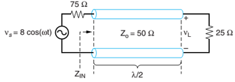
Figure 6.51 Complete circuit for Problem 6.18.
Expert Solution & Answer
Want to see the full answer?
Check out a sample textbook solution
Students have asked these similar questions
Which Transmission Line Parameter is neglected or ignored in most classifications of Transmission Line Equivalent Circuits?
A.
The Line Inductance
B.
The Line Resistance
C.
The Shunt Conductance
D.
The Shunt Capacitance
g) Why the Capacitance effect is neglected
in Short Transmission Line.
h) Distinguish between Lumped or
Distributed elements in a Transmission Line.
Expression for a voltage reflection co-efficient in terms of load impedance and characteristics impedance is:
a) (ZL- Zo)/(ZL+ Zo)
b) (Z+ Zo)/(ZL- Z)
c) ZĻ. Zo/( Z+ Zo)( ZL-Zo)
d) (ZL+ Zo)( ZL-Zo ZL. Zo
Chapter 6 Solutions
Fundamentals of Electromagnetics with Engineering Applications
Ch. 6 - Prob. 6.1PCh. 6 - Prob. 6.2PCh. 6 - Modify (6.3) to include internal inductance of the...Ch. 6 - Prob. 6.5PCh. 6 - The specifications for RG-214 coaxial cable are as...Ch. 6 - For the RG-214 coax of Problem 6.6 operating at...Ch. 6 - If 1.0 W of power is inserted into a coaxial...Ch. 6 - Starting with a 1 .0-mm-diameter solid copper...Ch. 6 - A coaxial cable has a solid copper inner conductor...Ch. 6 - Prob. 6.11P
Ch. 6 - Prob. 6.12PCh. 6 - Prob. 6.13PCh. 6 - A source with 50- source impedance drives a 50-...Ch. 6 - Prob. 6.15PCh. 6 - Prob. 6.16PCh. 6 - The input impedance for a 30.-cm length of...Ch. 6 - For the lossless T-line circuit shown in Figure...Ch. 6 - Prob. 6.19PCh. 6 - Prob. 6.20PCh. 6 - Prob. 6.21PCh. 6 - Repeat Problem 6.14 using the Smith Chart.Ch. 6 - Prob. 6.23PCh. 6 - Prob. 6.24PCh. 6 - Prob. 6.25PCh. 6 - On a 50- lossless T-line, the VSWR is measured as...Ch. 6 - Prob. 6.27PCh. 6 - Prob. 6.28PCh. 6 - Referring to Figure 6.20, suppose we measure...Ch. 6 - A matching network, using a reactive element in...Ch. 6 - A matching network consists of a length of T-line...Ch. 6 - You would like to match a 170- load to a 50-...Ch. 6 - A load impedance ZL=200+j160 is to be matched to a...Ch. 6 - Repeat Problem 6.34 for an open-ended shunt-stub...Ch. 6 - A load impedance ZL=25+j90 is to be matched to a...Ch. 6 - Repeat Problem 6.36 for an open-ended shunt-stub...Ch. 6 - Prob. 6.38PCh. 6 - Prob. 6.39PCh. 6 - Prob. 6.40PCh. 6 - Prob. 6.41PCh. 6 - Prob. 6.42PCh. 6 - Prob. 6.43PCh. 6 - Prob. 6.44PCh. 6 - Prob. 6.45PCh. 6 - Prob. 6.46PCh. 6 - The top-down view of a microstrip circuit is shown...Ch. 6 - Prob. 6.48PCh. 6 - Prob. 6.49PCh. 6 - Prob. 6.50PCh. 6 - Prob. 6.51PCh. 6 - Prob. 6.53PCh. 6 - Prob. 6.54PCh. 6 - Prob. 6.55PCh. 6 - Prob. 6.56PCh. 6 - Prob. 6.57PCh. 6 - Actual pulses have some slope to the leading and...Ch. 6 - Prob. 6.59P
Knowledge Booster


Learn more about
Need a deep-dive on the concept behind this application? Look no further. Learn more about this topic, electrical-engineering and related others by exploring similar questions and additional content below.Similar questions
- 6.5. A three phase 50 Hz transmission line has impedance of (25.3 + j66.5) ohms and a shunt admittance of 4.42 x 10 mho per phase. If it delivers a load of 50 MW at 220 kV at 0.8 power factor lagging, determine the sending end voltage (a) by short line approximation (b) nominal II method (c) exact transmission line equations. Ans. (a) 233.8 2.2° kV, (b) 232.2 2.33°, (c) 230.52 2.50° kV,arrow_forward6.8. A three phase, 50 Hz, 100 km transmission line has resistance 0.1 ohms/km, inductance 111.7 mH/km and capacitance 0.9954 x 10- uF/ph per km. The line is delivering 20 MW at a 0.8 power factor lagging and 66 kV to a balanced load. Determine the efficiency and regulation. Use nominal it method. Ans. n= 93.5%, VR = 17.47%arrow_forward6-A lossless T.L. has Zo = 100 N and is loaded by an unknown impedance Its VSWR is 4 and the first voltage maximum is A/8 from the load . Find the load impedance .arrow_forward
- a line characteristic impedance 600 ohm and 3 db loss is a half wavelength .it is fed by a source of emf 5v and impedance 1 kilo ohm and is terminated by aload 0f 400 ohms impedance .calculate the load voltage ..arrow_forwardWhat are the applications for stripline and microstrip transmission lines, and could you provide two examples of characteristic impedance application for each type of transmission line?arrow_forward5-A lossless T.L. has Zo = 100 Q and is loaded by ZL. The VSWR = 2. The first two voltage minima are located at z= -10 and -35 Cm from the load where z = 0. Determine ZL.arrow_forward
- "Transmission lines theory", explain with it; transmission lines effects and their causes,arrow_forward"In medium transmission line modeling, which of the parameter is considered to be lumped?" Resistance Inductance Capacitance All options are correctarrow_forwardHow does inductance impact the performance of a transmission line in terms of signal integrity and power losses?arrow_forward
- A DC generator of voltage Vg and internal resistance Rg is connected to a lossy transmission line characterised by a resistance per unit length R and a conductance per unit length G. a.)Write the governing voltage and current transmission line eequations. b.)Find the general solutions for v(z) and I(z). c.)Specialise the solutions in part(b) to those for an infinte line. d.)Specialize the solutions in part(b) to those for a finite line of length l that is terminated in a load resistance Rl.arrow_forwardIdeally, a dc load line is a straight line drawn on collector characteristic curves between which of the following? Please select one: a. Q Point and shear b. Q Point and saturation c. V_CE (interrupt) and I_C (sat) d. I_b = 0 and I_B = I_C/ß_DCarrow_forward6.11. In the two-bus system shown in Figure 6.24, bus 1 is a slack bus with V₁ = 1.020° pu. A load of 100 MW and 50 Mvar is taken from bus 2. The line impedance is z12 = 0.12 + j0.16 pu on a base of 100 MVA. Using Newton- Raphson method, obtain the voltage magnitude and phase angle of bus 2. Start with an initial estimate of |V₂|(0) = 1.0 pu and 8₂ (0) two iterations. 0°. Perform 2 *12 = 0 12 + j0.16 Note 100 MW -+-) 50 Myar Perform Second iteration I have problem while solving it 어 V = 1.040° FIGURE 6.24 One-line diagram for Problem 6.11.. U(¹) = 0.8 Pu ops 62 = -1.0 radionarrow_forward
arrow_back_ios
SEE MORE QUESTIONS
arrow_forward_ios
Recommended textbooks for you
 Power System Analysis and Design (MindTap Course ...Electrical EngineeringISBN:9781305632134Author:J. Duncan Glover, Thomas Overbye, Mulukutla S. SarmaPublisher:Cengage Learning
Power System Analysis and Design (MindTap Course ...
Electrical Engineering
ISBN:9781305632134
Author:J. Duncan Glover, Thomas Overbye, Mulukutla S. Sarma
Publisher:Cengage Learning
How do Electric Transmission Lines Work?; Author: Practical Engineering;https://www.youtube.com/watch?v=qjY31x0m3d8;License: Standard Youtube License