
Mechanics of Materials (MindTap Course List)
9th Edition
ISBN: 9781337093347
Author: Barry J. Goodno, James M. Gere
Publisher: Cengage Learning
expand_more
expand_more
format_list_bulleted
Concept explainers
Videos
Textbook Question
Chapter 5, Problem 5.7.8P
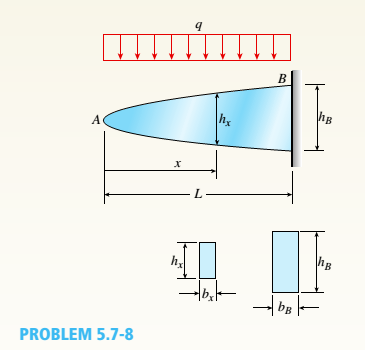
A cantilever beam AB having rectangular cross sections with varying width bxand varying height hxis subjected to a uniform load of intensity q (sec figure). If the width varies linearly with x according to the equation hx= bBxiL^ how should the height hxvary as a function of v in order to have a fully stressed beam? (Express hxin terms of the height hBat the fixed end of the beam.)
Expert Solution & Answer

Trending nowThis is a popular solution!

Chapter 5 Solutions
Mechanics of Materials (MindTap Course List)
Ch. 5 - A steel wire with a diameter of d = 1/16 in. is...Ch. 5 - A copper wire having a diameter ofd = 4 mm is bent...Ch. 5 - A 4.75-in, outside diameter polyethylene pipe...Ch. 5 - A cantilever beam AB is loaded by a couple M0at...Ch. 5 - A thin strip of steel with a length of L =19 in....Ch. 5 - A bar of rectangular cross section is loaded and...Ch. 5 - A simply supported beam with a length L = 10 ft...Ch. 5 - A cantilever beam is subjected to a concentrated...Ch. 5 - A thin strip of hard copper (E = 16,000 ksi)...Ch. 5 - A steel wire (E = 200 GPa) of a diameter d = L25...
Ch. 5 - A thin, high-strength steel rule (E = 30 x 10ft...Ch. 5 - A simply supported wood beam AB with a span length...Ch. 5 - Beam ABC has simple supports at A and B and an...Ch. 5 - A simply supported beam is subjected to a in early...Ch. 5 - Each girder of the lift bridge (sec figure) is 180...Ch. 5 - A freight-car axle AS is loaded approximately as...Ch. 5 - A seesaw weighing 3 lb/ft of length is occupied by...Ch. 5 - During construction of a highway bridge, the main...Ch. 5 - The horizontal beam ABC of an oil-well pump has...Ch. 5 - A railroad tie (or sleeper) is subjected to two...Ch. 5 - A fiberglass pipe is lifted by a sling, as shown...Ch. 5 - A small dam of height h = 2.0 m is constructed of...Ch. 5 - Determine the maximum tensile stress (7, (due to...Ch. 5 - Determine the maximum bending stress emaxdue to...Ch. 5 - A simple beam A B of a span length L = 24 ft is...Ch. 5 - Determine the maximum tensile stress erand maximum...Ch. 5 - A cantilever beam A3, loaded by a uniform load and...Ch. 5 - A canti lever beam A B of a n isosceles t...Ch. 5 - A cantilever beam, a C12 x 30 section, is...Ch. 5 - A frame ABC travels horizontally with an...Ch. 5 - A beam ABC with an overhang from B to C supports a...Ch. 5 - A cantilever beam AB with a rectangular cross...Ch. 5 - A beam with a T-section is supported and loaded as...Ch. 5 - Consider the compound beam with segments AB and...Ch. 5 - A small dam of a height h = 6 ft is constructed of...Ch. 5 - A foot bridge on a hiking trail is constructed...Ch. 5 - A steel post (E=30×106) having thickness t = 1/8...Ch. 5 - Beam ABCDE has a moment release just right of...Ch. 5 - A simply supported wood beam having a span length...Ch. 5 - A simply supported beam (L = 4.5 m) must support...Ch. 5 - The cross section of a narrow-gage railway bridge...Ch. 5 - A fiberglass bracket A BCD with a solid circular...Ch. 5 - A cantilever beanie B is loaded by a uniform load...Ch. 5 - A simple beam of length L = 5 m carries a uniform...Ch. 5 - A simple beam AB is loaded as shown in the figure....Ch. 5 - A pontoon bridge (see figure) is constructed of...Ch. 5 - A floor system in a small building consists of...Ch. 5 - The wood joists supporting a plank Floor (see...Ch. 5 - A beam ABC with an overhang from B to C is...Ch. 5 - -12 A "trapeze bar" in a hospital room provides a...Ch. 5 - A two-axle carriage that is part of an over head...Ch. 5 - A cantilever beam AB with a circular cross section...Ch. 5 - A propped cantilever beam A BC (see figure) has a...Ch. 5 - A small balcony constructed of wood is supported...Ch. 5 - A beam having a cross section in the form of an un...Ch. 5 - A beam having a cross section in the form of a...Ch. 5 - Determine the ratios of the weights of four beams...Ch. 5 - Prob. 5.6.20PCh. 5 - A steel plate (called a cover ploie) having...Ch. 5 - A steel beam ABC is simply supported at A and...Ch. 5 - A retaining wall 6 ft high is constructed of...Ch. 5 - A retaining wall (Fig. a) is constructed using...Ch. 5 - A beam of square cross section (a = length of each...Ch. 5 - The cross section of a rectangular beam having a...Ch. 5 - A tapered cantilever beam A B of length L has...Ch. 5 - .2 A ligmio.irc ii supported by two vorlical beams...Ch. 5 - Prob. 5.7.3PCh. 5 - Prob. 5.7.4PCh. 5 - Prob. 5.7.5PCh. 5 - A cantilever beam AB with rectangular cross...Ch. 5 - A simple beam ABC having rectangular cross...Ch. 5 - A cantilever beam AB having rectangular cross...Ch. 5 - The shear stresses t in a rectangular beam arc...Ch. 5 - .2 Calculate the maximum shear stress tmaxand the...Ch. 5 - A simply supported wood beam is subjected to...Ch. 5 - A simply supported wood beam with overhang is...Ch. 5 - Two wood beams, each of rectangular cross section...Ch. 5 - A cantilever beam of length L = 2 m supports a...Ch. 5 - A steel beam of length L = 16 in. and...Ch. 5 - A beam of rectangular cross section (width/) and...Ch. 5 - A laminated wood beam on simple supports (figure...Ch. 5 - A laminated plastic beam of square cross section...Ch. 5 - A wood beam AB on simple supports with span length...Ch. 5 - A simply supported wood beam of rectangular cross...Ch. 5 - A square wood platform is 8 ft × 8 ft in area and...Ch. 5 - A wood beam ABC with simple supports at A and B...Ch. 5 - A wood pole with a solid circular cross section (d...Ch. 5 - A simple log bridge in a remote area consists of...Ch. 5 - A vertical pole consisting of a circular tube of...Ch. 5 - A circular pole is subjected to linearly varying...Ch. 5 - A sign for an automobile service station is...Ch. 5 - A steel pipe is subjected to a quadratic...Ch. 5 - -1 through 5.10-6 A wide-flange beam (see figure)...Ch. 5 - -1 through 5.10-6 A wide-flange beam (see figure)...Ch. 5 - -1 through 5.10-6 A wide-flange beam (see figure)...Ch. 5 - -1 through 5.10-6 A wide-flange beam (see figure)...Ch. 5 - -1 through 5.10-6 A wide-flange beam (see figure)...Ch. 5 - -1 through 5.10-6 A wide-flange beam (see figure)...Ch. 5 - A cantilever beam AB of length L = 6.5 ft supports...Ch. 5 - A bridge girder A B on a simple span of length L =...Ch. 5 - A simple beam with an overhang supports a uniform...Ch. 5 - A hollow steel box beam has the rectangular cross...Ch. 5 - A hollow aluminum box beam has the square cross...Ch. 5 - The T-beam shown in the figure has cross-sectional...Ch. 5 - Calculate the maximum shear stress tmax. in the...Ch. 5 - A prefabricated wood I-beam serving as a floor...Ch. 5 - A welded steel gird crhaving the erass section...Ch. 5 - A welded steel girder having the cross section...Ch. 5 - A wood box beam is constructed of two 260 mm × 50...Ch. 5 - A box beam is constructed of four wood boards as...Ch. 5 - Two wood box beams (beams A and B) have the same...Ch. 5 - A hollow wood beam with plywood webs has the...Ch. 5 - A beam of a T cross section is formed by nailing...Ch. 5 - The T-beam shown in the figure is fabricated by...Ch. 5 - A steel beam is built up from a W 410 × 85 wide...Ch. 5 - The three beams shown have approximately the same...Ch. 5 - Two W 310 × 74 Steel wide-flange beams are bolted...Ch. 5 - A pole is fixed at the base and is subjected to a...Ch. 5 - A solid circular pole is subjected to linearly...Ch. 5 - While drilling a hole with a brace and bit, you...Ch. 5 - An aluminum pole for a street light weighs 4600 N...Ch. 5 - A curved bar ABC having a circular axis (radius r...Ch. 5 - A rigid Trame ABC is formed by welding two steel...Ch. 5 - A palm tree weighing 1000 lb is inclined at an...Ch. 5 - A vertical pole of aluminum is fixed at the base...Ch. 5 - Because of foundation settlement, a circular tower...Ch. 5 - A steel bracket of solid circular cross section is...Ch. 5 - A cylindrical brick chimney of height H weighs w =...Ch. 5 - A flying but tress transmit s a load P = 25 kN,...Ch. 5 - A plain concrete wall (i.e., a wall with no steel...Ch. 5 - A circular post, a rectangular post, and a post of...Ch. 5 - Two cables, each carrying a tensile force P = 1200...Ch. 5 - Prob. 5.12.16PCh. 5 - A short column constructed of a W 12 × 35...Ch. 5 - A short column with a wide-flange shape is...Ch. 5 - A tension member constructed of an L inch angle...Ch. 5 - A short length of a C 200 × 17.1 channel is...Ch. 5 - The beams shown in the figure are subjected to...Ch. 5 - The beams shown in the figure are subjected to...Ch. 5 - A rectangular beam with semicircular notches, as...Ch. 5 - A rectangular beam with semicircular notches, as...Ch. 5 - A rectangular beam with notches and a hole (see...
Knowledge Booster


Learn more about
Need a deep-dive on the concept behind this application? Look no further. Learn more about this topic, mechanical-engineering and related others by exploring similar questions and additional content below.Similar questions
- A fixed-end beam AB of a length L supports a uniform load of intensity q (see figure). Beginning with the second-order differential equation of the deflection curve (the bending-moment equation), obtain the reactions, shear forces, bending moments, slopes, and deflections of the beam. Construct the shear-force and bending-moment diagrams, Labeling all critical ordinales.arrow_forwardBeam ACB hangs from two springs, as shown in the figure. The springs have stiffnesses Jt(and k2^ and the beam has flexural rigidity EI. What is the downward displacement of point C, which is at the midpoint of the beam, when the moment MQis applied? Data for the structure are M0 = 7.5 kip-ft, L = 6 ft, EI = 520 kip-ft2, kx= 17 kip/ft, and As = 11 kip/ft. Repeat part (a), but remove Af0 and instead apply uniform load q over the entire beam.arrow_forwardCantilever beam AB carries an upward uniform load of intensity q1from x = 0 to L/2 (see Fig. a) and a downward uniform load of intensity q from x = L/2 to L. Find q1in terms of q if the resulting moment at A is zero. Draw V and M diagrams for the case of both q and qtas applied loadings. Repeat part (a) for the case of an upward triangularly distributed load with peak intensity q0(see Fig. b). For part (b), find q0, instead of q1arrow_forward
- A fixed-end beam AB of a length L is subjected to a uniform load of intensity q acting over the middle region of the beam (sec figure). Obtain a formula for the fixed-end moments MAand MBin terms of the load q, the length L, and the length h of the loaded part of the beam. Plot a graph of the fixed-end moment MAversus the length b of the loaded part of the beam. For convenience, plot the graph in the following nondimensional form: MAqL2/l2versusbL with the ratio b/L varying between its extreme values of 0 and 1. (c) For the special case in which ù = h = L/3, draw the shear-force and bending-moment diagrams for the beam, labeling all critical ordinates.arrow_forwardBeam ABCD represents a reinforced-concrete foundation beam that supports a uniform load of intensity q1= 3500 lb/ft (see figure). Assume that the soil pressure on the underside of the beam is uniformly distributed with intensity q2 Find the shear force VBand bending moment MBat point B. Find the shear force Vmand bending moment M at the midpoint of the beam.arrow_forwardA cantilever beam model is often used to represent micro-clectrical-mechanical systems (MEMS) (sec figure}. The cantilever beam is made of polysilicon (E = 150 GPa) and is subjected to an electrostatic moment M applied at the end of the cantilever beam. 1 f dimensions arc h — 2 [im, h — 4 ^m, and L = 520 ^mt find expressions for the tip deflection and rotation of the cantilever beam in terms of moment M.arrow_forward
- A fixed-end beam AB carries point load P acting at point C. The beam has a rectangular cross section (b = 75 mm, h = 150 mm). Calculate the reactions of the beam and the displacement at point C. Assume that E = 190 GPa.arrow_forward(a) A simple beam AB with length L and height h supports a uniform load of intensity q (see the figure part a). Obtain a formula for the curvature shortening A of this beam. Also, obtain a formula for the maximum bending stress b in the beam due to the load q. Now assume that the ends of the beam are pinned so that curvature shortening is prevented and a horizontal force H develops at the supports (see the figure part b). Obtain a formula for the corresponding axial tensile stress t . Using the formulas obtained in parts (a) and (b), calculate the curvature shortening , the maximum bending stress b, and the tensile stress t for the following steel beam: length L = 3m, height h = 300 mm, modulus of elasticity E = 200 GPa, and moment of inertia I = 36 x 106 mm4. Also, the load on the beam has intensity q = 25 kN/m. Compare the tensile stress tproduced by the axial forces with the maximum bending stress bproduced by the uniform load.arrow_forwardA singly symmetric beam with a T-section (see figure) has cross-sectional dimensions b = 140 mm, a = 190, 8 mm, b. = 6,99 mm, and fc = 11,2 mm. Calculate the plastic modulus Z and the shape factor.arrow_forward
- A cantilever beam of a length L and loaded by a uniform load of intensity q has a fixed support at A and spring support at B with rotational stiffness kR. A rotation B at B results in a reaction moment MB=kRxB. Find rotation B and displacement Bat end B. Use the second-order differential equation of the deflection curve to solve for displacements at end B.arrow_forwardBeam ABC is fixed at support A and rests (at point B) upon the midpoint of beam DE (see part a of the figure). Thus, beam, ABC may be represented as a propped cantilever beam with an overhang BC and a linearly elastic support of stiffness k at point B (see part b of the figure). The distance from A to B is L = 10 ft, the distance from B to C is L/2 = 5 ft, and the length of beam DE is L = 10 ft. Both beams have the same flexural rigidity EI. A concentrated load P = 1700 lb acts at t lie free end of beam ABC. Determine the reactions RA, RB+ and MAfor beam ABC. Also, draw the shear-force and bending-moment diagrams for beam ABC, labeling all critical ordinates.arrow_forwardA counterclockwise moment M0acts at the midpoint of a fixed-end beam ACB of length L (see figure). Beginning with the second-order differential equation of the deflection curve (the bendingmoment equation), determine all reactions of the beam and obtain the equation of the deflection curve for the left-hand half of the beam. Then construct the shear-force and bending-moment diagrams for the entire beam, labeling all critical ordinales. Also, draw the deflection curve for the entire beam.arrow_forward
arrow_back_ios
SEE MORE QUESTIONS
arrow_forward_ios
Recommended textbooks for you
 Mechanics of Materials (MindTap Course List)Mechanical EngineeringISBN:9781337093347Author:Barry J. Goodno, James M. GerePublisher:Cengage Learning
Mechanics of Materials (MindTap Course List)
Mechanical Engineering
ISBN:9781337093347
Author:Barry J. Goodno, James M. Gere
Publisher:Cengage Learning
Solids: Lesson 53 - Slope and Deflection of Beams Intro; Author: Jeff Hanson;https://www.youtube.com/watch?v=I7lTq68JRmY;License: Standard YouTube License, CC-BY