
Mechanics of Materials (MindTap Course List)
9th Edition
ISBN: 9781337093347
Author: Barry J. Goodno, James M. Gere
Publisher: Cengage Learning
expand_more
expand_more
format_list_bulleted
Concept explainers
Videos
Textbook Question
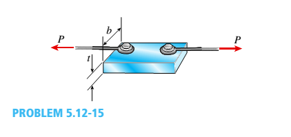
Chapter 5, Problem 5.12.15P
Two cables, each carrying a tensile force P = 1200 lb, are bolted to a block of steel (see figure). The block has thickness i = 1 in. and width b = 3 in.
- If the diameter d of the cable is 0.25 in., what are the maximum tensile and compressive stresses e1and e2., respectively, in the block?
- If the diameter of the cable is increased (without changing the force P), what happens to the maximum tensile and compressive stresses?
Expert Solution & Answer

Trending nowThis is a popular solution!

Chapter 5 Solutions
Mechanics of Materials (MindTap Course List)
Ch. 5 - A steel wire with a diameter of d = 1/16 in. is...Ch. 5 - A copper wire having a diameter ofd = 4 mm is bent...Ch. 5 - A 4.75-in, outside diameter polyethylene pipe...Ch. 5 - A cantilever beam AB is loaded by a couple M0at...Ch. 5 - A thin strip of steel with a length of L =19 in....Ch. 5 - A bar of rectangular cross section is loaded and...Ch. 5 - A simply supported beam with a length L = 10 ft...Ch. 5 - A cantilever beam is subjected to a concentrated...Ch. 5 - A thin strip of hard copper (E = 16,000 ksi)...Ch. 5 - A steel wire (E = 200 GPa) of a diameter d = L25...
Ch. 5 - A thin, high-strength steel rule (E = 30 x 10ft...Ch. 5 - A simply supported wood beam AB with a span length...Ch. 5 - Beam ABC has simple supports at A and B and an...Ch. 5 - A simply supported beam is subjected to a in early...Ch. 5 - Each girder of the lift bridge (sec figure) is 180...Ch. 5 - A freight-car axle AS is loaded approximately as...Ch. 5 - A seesaw weighing 3 lb/ft of length is occupied by...Ch. 5 - During construction of a highway bridge, the main...Ch. 5 - The horizontal beam ABC of an oil-well pump has...Ch. 5 - A railroad tie (or sleeper) is subjected to two...Ch. 5 - A fiberglass pipe is lifted by a sling, as shown...Ch. 5 - A small dam of height h = 2.0 m is constructed of...Ch. 5 - Determine the maximum tensile stress (7, (due to...Ch. 5 - Determine the maximum bending stress emaxdue to...Ch. 5 - A simple beam A B of a span length L = 24 ft is...Ch. 5 - Determine the maximum tensile stress erand maximum...Ch. 5 - A cantilever beam A3, loaded by a uniform load and...Ch. 5 - A canti lever beam A B of a n isosceles t...Ch. 5 - A cantilever beam, a C12 x 30 section, is...Ch. 5 - A frame ABC travels horizontally with an...Ch. 5 - A beam ABC with an overhang from B to C supports a...Ch. 5 - A cantilever beam AB with a rectangular cross...Ch. 5 - A beam with a T-section is supported and loaded as...Ch. 5 - Consider the compound beam with segments AB and...Ch. 5 - A small dam of a height h = 6 ft is constructed of...Ch. 5 - A foot bridge on a hiking trail is constructed...Ch. 5 - A steel post (E=30×106) having thickness t = 1/8...Ch. 5 - Beam ABCDE has a moment release just right of...Ch. 5 - A simply supported wood beam having a span length...Ch. 5 - A simply supported beam (L = 4.5 m) must support...Ch. 5 - The cross section of a narrow-gage railway bridge...Ch. 5 - A fiberglass bracket A BCD with a solid circular...Ch. 5 - A cantilever beanie B is loaded by a uniform load...Ch. 5 - A simple beam of length L = 5 m carries a uniform...Ch. 5 - A simple beam AB is loaded as shown in the figure....Ch. 5 - A pontoon bridge (see figure) is constructed of...Ch. 5 - A floor system in a small building consists of...Ch. 5 - The wood joists supporting a plank Floor (see...Ch. 5 - A beam ABC with an overhang from B to C is...Ch. 5 - -12 A "trapeze bar" in a hospital room provides a...Ch. 5 - A two-axle carriage that is part of an over head...Ch. 5 - A cantilever beam AB with a circular cross section...Ch. 5 - A propped cantilever beam A BC (see figure) has a...Ch. 5 - A small balcony constructed of wood is supported...Ch. 5 - A beam having a cross section in the form of an un...Ch. 5 - A beam having a cross section in the form of a...Ch. 5 - Determine the ratios of the weights of four beams...Ch. 5 - Prob. 5.6.20PCh. 5 - A steel plate (called a cover ploie) having...Ch. 5 - A steel beam ABC is simply supported at A and...Ch. 5 - A retaining wall 6 ft high is constructed of...Ch. 5 - A retaining wall (Fig. a) is constructed using...Ch. 5 - A beam of square cross section (a = length of each...Ch. 5 - The cross section of a rectangular beam having a...Ch. 5 - A tapered cantilever beam A B of length L has...Ch. 5 - .2 A ligmio.irc ii supported by two vorlical beams...Ch. 5 - Prob. 5.7.3PCh. 5 - Prob. 5.7.4PCh. 5 - Prob. 5.7.5PCh. 5 - A cantilever beam AB with rectangular cross...Ch. 5 - A simple beam ABC having rectangular cross...Ch. 5 - A cantilever beam AB having rectangular cross...Ch. 5 - The shear stresses t in a rectangular beam arc...Ch. 5 - .2 Calculate the maximum shear stress tmaxand the...Ch. 5 - A simply supported wood beam is subjected to...Ch. 5 - A simply supported wood beam with overhang is...Ch. 5 - Two wood beams, each of rectangular cross section...Ch. 5 - A cantilever beam of length L = 2 m supports a...Ch. 5 - A steel beam of length L = 16 in. and...Ch. 5 - A beam of rectangular cross section (width/) and...Ch. 5 - A laminated wood beam on simple supports (figure...Ch. 5 - A laminated plastic beam of square cross section...Ch. 5 - A wood beam AB on simple supports with span length...Ch. 5 - A simply supported wood beam of rectangular cross...Ch. 5 - A square wood platform is 8 ft × 8 ft in area and...Ch. 5 - A wood beam ABC with simple supports at A and B...Ch. 5 - A wood pole with a solid circular cross section (d...Ch. 5 - A simple log bridge in a remote area consists of...Ch. 5 - A vertical pole consisting of a circular tube of...Ch. 5 - A circular pole is subjected to linearly varying...Ch. 5 - A sign for an automobile service station is...Ch. 5 - A steel pipe is subjected to a quadratic...Ch. 5 - -1 through 5.10-6 A wide-flange beam (see figure)...Ch. 5 - -1 through 5.10-6 A wide-flange beam (see figure)...Ch. 5 - -1 through 5.10-6 A wide-flange beam (see figure)...Ch. 5 - -1 through 5.10-6 A wide-flange beam (see figure)...Ch. 5 - -1 through 5.10-6 A wide-flange beam (see figure)...Ch. 5 - -1 through 5.10-6 A wide-flange beam (see figure)...Ch. 5 - A cantilever beam AB of length L = 6.5 ft supports...Ch. 5 - A bridge girder A B on a simple span of length L =...Ch. 5 - A simple beam with an overhang supports a uniform...Ch. 5 - A hollow steel box beam has the rectangular cross...Ch. 5 - A hollow aluminum box beam has the square cross...Ch. 5 - The T-beam shown in the figure has cross-sectional...Ch. 5 - Calculate the maximum shear stress tmax. in the...Ch. 5 - A prefabricated wood I-beam serving as a floor...Ch. 5 - A welded steel gird crhaving the erass section...Ch. 5 - A welded steel girder having the cross section...Ch. 5 - A wood box beam is constructed of two 260 mm × 50...Ch. 5 - A box beam is constructed of four wood boards as...Ch. 5 - Two wood box beams (beams A and B) have the same...Ch. 5 - A hollow wood beam with plywood webs has the...Ch. 5 - A beam of a T cross section is formed by nailing...Ch. 5 - The T-beam shown in the figure is fabricated by...Ch. 5 - A steel beam is built up from a W 410 × 85 wide...Ch. 5 - The three beams shown have approximately the same...Ch. 5 - Two W 310 × 74 Steel wide-flange beams are bolted...Ch. 5 - A pole is fixed at the base and is subjected to a...Ch. 5 - A solid circular pole is subjected to linearly...Ch. 5 - While drilling a hole with a brace and bit, you...Ch. 5 - An aluminum pole for a street light weighs 4600 N...Ch. 5 - A curved bar ABC having a circular axis (radius r...Ch. 5 - A rigid Trame ABC is formed by welding two steel...Ch. 5 - A palm tree weighing 1000 lb is inclined at an...Ch. 5 - A vertical pole of aluminum is fixed at the base...Ch. 5 - Because of foundation settlement, a circular tower...Ch. 5 - A steel bracket of solid circular cross section is...Ch. 5 - A cylindrical brick chimney of height H weighs w =...Ch. 5 - A flying but tress transmit s a load P = 25 kN,...Ch. 5 - A plain concrete wall (i.e., a wall with no steel...Ch. 5 - A circular post, a rectangular post, and a post of...Ch. 5 - Two cables, each carrying a tensile force P = 1200...Ch. 5 - Prob. 5.12.16PCh. 5 - A short column constructed of a W 12 × 35...Ch. 5 - A short column with a wide-flange shape is...Ch. 5 - A tension member constructed of an L inch angle...Ch. 5 - A short length of a C 200 × 17.1 channel is...Ch. 5 - The beams shown in the figure are subjected to...Ch. 5 - The beams shown in the figure are subjected to...Ch. 5 - A rectangular beam with semicircular notches, as...Ch. 5 - A rectangular beam with semicircular notches, as...Ch. 5 - A rectangular beam with notches and a hole (see...
Knowledge Booster


Learn more about
Need a deep-dive on the concept behind this application? Look no further. Learn more about this topic, mechanical-engineering and related others by exploring similar questions and additional content below.Similar questions
- Wires B and C are attached to a support at the left-hand end and to a pin-supported rigid bar at the right-hand end (see figure). Each wire has cross-sectional area A =0.03 in2 and modulus of elasticity E = 30 X 106 psi. When the bar is in a vertical position, the length of each wire is L = 80 in. However, before being attached to the bar, the length of wire B was 79.98 in. and wire C was 79.95 in. Find the tensile forces TBand Tc in the wires under the action of a force P = 700 lb acting at the upper end of the bar.arrow_forwardBy what distance h does the cage shown in the figure move downward when the weight W is placed inside it? (See the figure.) Consider only the effects of the stretching of the cable, which has axial rigidity EA = 10,700 kN. The pulley at A has a diameter da= 300 mm and the pulley at B has a diameter dB= 150 mm. Also, the distance L1= 4.6 m, the distance L2=10.5 m, and the weight W = 22 kN. Note: When calculating the length of the cable. include the parts of the cable that go around the pulley sat A and B.arrow_forwardA flat brass bar has length L, constant thickness t, and a rectangular cross section whose width varies linearly between b2at the fixed support to b1at the free end (see figure). Assume that the taper of the bar is small. The bar has modulus of elasticity E. Calculate the displacements ??Band ??cif P = 200 kN, L = 2 m, t = 20 mm, b, = 100 mm, b, = 115 mm, and E = 96 GPa.arrow_forward
- A plane frame with a pin support at A and roller supports at C and £ has a cable attached at E. which runs over Frictionless pulleys al D and B (see figure). The cable force is known to be 400 N. There is a pin connection just Lo the left of joint C. (a) Find reactions at supports^, C, and E. (b) Find internal stress, resultants N, V, and M just to the right of joint C. (c) Find resultant force in the pin near C.arrow_forwardPlastic bar of diameter d = 32 mm is compressed in a testing device by a Force P = 190 N that is applied as shown in the figure. (a) Determine the normal and shear stresses acting: on all faces of stress elements oriented at (1 ) an angle 8 = 00, (2) an angle ?? = 22.5s, and (3) an angle ?? = 45°. In each case, show the stresses on a sketch of a properly oriented element. What are smaxtmax (b) Find smax and tmax in the plastic bar if a re-cantering spring of stiffness k is inserted into the testing device, as shown in the figure. The spring stillness is 1/6 of the axial stiffness of the plastic bar.arrow_forwardA cylindrical pressure vessel having a radius r = 14 in. and wall thickness t = 0,5 in, is subjected to internal pressure p = 375 psi, In addition, a torque T = 90 kip-ft acts at each end of the cylinder (see figure), (a) Determine the maximum tensile stress ctniXand the maximum in-plane shear stress Tmjv in the wall of the cylinder. (b) If the allowable in-plane shear stress is 4.5 ksi, what is the maximum allowable torque T\ (c) If 7 = 150 kip-ft and allowable in-plane shear and allowable normal stresses are 4.5 ksi and 11.5 ksi, respectively, what is the minimum required wall thicknessarrow_forward
- A copper bar with a rectangular cross section is held without stress between rigid supports (see figure). Subsequently, the temperature of the bar is raised 50°C (a) Determine the stresses on all faces of the elements A and B, and show these stresses on sketches of the elements. (Assume = 17.5 × 10⁻⁶/? and E = 120 GPa ) (b) If the shear stress at B is known to be 48 MPa at some inclination 8, find anglearrow_forwardThree prismatic bars, two of material A and one of material B. transmit a tensile load P (see figure). The two outer bars (material A) are identical. The cross-sectional area of the middle bar (material B) is 50% larger than the cross-sectional area of one of the outer bars. Also, the modulus of elasticity of material A is twice that of material B. (a) What fraction of the load P is transmitted by the middle bar? (b) What is the ratio of the stress in the middle bar to the stress in the outer bars? (c) What is the ratio of the strain in the middle bar to the strain in the outer bars?arrow_forwardA circular aluminum tube of length L = 600 mm is loaded in compression by forces P (see figure). The outside and inside diameters are d2= 75 mm and d1= 63 mm, respectively. A strain gage is placed on the outside of the lube to measure normal strains in the longitudinal direction. Assume that E = 73 GPa and Poissons ratio is v = 0.33. (a) IF the compressive stress in the tube is 57 MPa, what is the load P? (b) If the measured strain is e = 78 J X 10-6, what is the shorteningarrow_forward
- Solve the preceding problem if the axial stress in the middle region is 24,000 psi, the length is 30 in., and the modulus of elasticity is 30 × 106 psi. In part (c), assume that dmax = 0.02 inarrow_forwardA prismatic bar AD of length L, cross-sectional area A. and modulus of elasticity E is subjected to loads 5P, 3P, and P acting at points B, C, and D, respectively (see figure). Segments AB, BC, and CD have lengths L/6, L/2, and L/3, respectively. (a) Obtain a formula for the strain energy U of the bar. (b) Calculate the strain energy if P = 6 kips, L = 52 in., A = 2.76 in2, and the material is aluminum with E = 10.4 × 10⁶ psi.arrow_forwardThe upper deck ala foothill stadium is supported by braces, each of which transfer a load P = 160 kips to the base of a column (see figure part a). A cap plate at the bottom of the brace distributes the load P to four flange pates (:1 = I in)t hrough a pin(d, = 2 in.) to two gusset plates t8 = l.5 in.) (see figure parts b and c). Determine the following quantities. (a) The average shear stress i in the pin. (b) The average bearing stress between the flange plates and the pin and also between the gusset plates and the pin Disregard friction between the plates. Determine the following quantities. (a) The average shear stress i in the pin. (b) The average bearing stress between the flange plates and the pin and also between the gusset plates and the pin (7j )L Disregard friction between the plates.arrow_forward
arrow_back_ios
SEE MORE QUESTIONS
arrow_forward_ios
Recommended textbooks for you
 Mechanics of Materials (MindTap Course List)Mechanical EngineeringISBN:9781337093347Author:Barry J. Goodno, James M. GerePublisher:Cengage Learning
Mechanics of Materials (MindTap Course List)
Mechanical Engineering
ISBN:9781337093347
Author:Barry J. Goodno, James M. Gere
Publisher:Cengage Learning
Column buckling; Author: Amber Book;https://www.youtube.com/watch?v=AvvaCi_Nn94;License: Standard Youtube License