Concept explainers
(a)
Plastic section modulus
Answer to Problem 5.2.1P
The plastic section modulus
Explanation of Solution
Given:
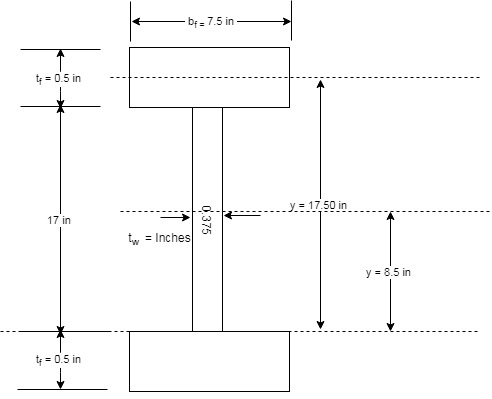
A flexural member is fabricated from two flange plates
Concept used:
The section is a symmetrical section which implies that the plastic neutral axis of the given section is same as the neutral of the given section. Therefore, calculating the lever arm and the centroid of the upper half of the given section, we can find the plastic section modulus.
We have the following figure that will define the terms that we have been given as per the question.

Calculation:
The following is the tabular measurement of every component required:
| Elements | |||||
| Web | |||||
| Flange | |||||
| Sum |
Calculating the centroid of the top half as :
Substitute the values in the above equation.
Now, calculating the moment arm, we have the following formula :
Where, a is the moment arm of the section.
Now, the plastic section modulus can be calculated as follows:
Where, Z is plastic section modulus and A is area.
Calculating the plastic moment as follows:
Substitute the value of
Conclusion:
Therefore, the plastic section modulus
(b)
Elastic section modulus,
Answer to Problem 5.2.1P
The elastic section modulus,
Explanation of Solution
Given:
A flexural member is fabricated from two flange plates
Concept used:
The section is a symmetrical section which implies that the elastic neutral axis of the given section is coinciding with the neutral of the given section. Therefore, calculating the moment of inertia at the major axis using parallel axis theorem, we can find the elastic section modulus.
We have the following figure that will define the terms that we have been given as per the question.
Calculation:
The following is the tabular measurement of every component required:
| Elements | ||||
| Web | ||||
| Top Flange | ||||
| Bottom Flange | ||||
| Sum |
Calculate the Elastic section modulus S with the following formula
Where, C is the distance between the extreme fiber of the section and the neutral axis and is equal to
Here,
By substituting the values in the above equation, we have
Substitute the value of c in the following equation,
Now, calculate the yield moment
Substitute the value of
Conclusion:
Therefore, the elastic section modulus,
Want to see more full solutions like this?
Chapter 5 Solutions
STEEL DESIGN (LOOSELEAF)


- The following steel circular bar (Es = 200 GPa) is divided into two segments. Segment 1 is tubular and segment 2 is solid. Determine the distance "x" so that the bar does not exceed a total deformation of 2.5 mm. The load P is equal to 25 kN, the diameter d is equal to 30 mm, and the length L is equal to 10 m.arrow_forwardDetermine the normal stress (in Mpa) in member AC of the truss shown if it is made up of a 22-mm-square bar of alloy and the load P is 20.15 kN. Express your answer in two decimal places.arrow_forwardA The member consists of the steel rod AB that is screwed into the end of the bronze rod BC. Find the largest value of P that meets the following design criteria: (i) the overall length of the member is not to change by more than 3 mm; and (ii) the stresses are not to exceed 140 MPa in steel and 120 MPa in bronze. The moduli of Problem 4: Steel A= 480 mm? 1.0 m B elasticity are 200 GPa for steel and 80 GPa for bronze. Problem 5: The compound bar carries the axial forces P and 2P. Find the maximum allowable value of P if the working stresses are 40 ksi for steel and 20 ksi for alumi- num, and the total elongation of the bar is not to exoceed 0.2 in. 3P Bronze A= 650 mm 2 m 3 ft 4 ft 2P Steel A = 0,4 in.2 E = 29 × 10° psi 2P Aluminum A = 0.6 in.2 E= 10 x 10° psiarrow_forward
- 6- For a simply supported beam with b=300 mm and d=500 mm, if f = 63MPa, f, = 280 MPa and the net tensile strain is greater than 0.005, then the maximum steel ratio equal............ (a) 0.0406 (b) 0.0310 (c) 0.0287 (d) 0.0180 (e) Nonearrow_forwardDetermine the force P necessary to close the gap at the steel post. The steel post is 2 inch x 2 inch square and 8 in high. The aluminum alloy bar is 1.5 inch wide by 1 inch thick and 20 in long. The horizontal bar is considered rigid as are the loading caps at the steel post. The modulus of elasticity for the steel is 30,000 ksi, that of aluminum is 10,000 ksi. The yield stress for the steel is 36 ksi, that of the aluminum is 40 ksi. 8" 10" Steel 10" Rigid Aluminum 20 inches long * P 10" Gap = 0.02 inchesarrow_forwardThe 10-mm-diameter steel bolt in (Figure 1) is surrounded by a bronze sleeve. The outer diameter of this sleeve is 20 mm, and its inner diameter is 10 mm. Est = 200 GPa, Ebr 100 GPa. Figure P P -10 mm -20 mm 1 of 1 Part A If the bolt is subjected to a compressive force of P = 21.9 kN, determine the magnitude of the average normal stress in the steel. Express your answer to three significant figures and include appropriate units. Ost = Submit Part B Obr = Submit 0 Value If the bolt is subjected to a compressive force of P = 21.9 kN, determine the magnitude of the average normal stress in the bronze. Express your answer to three significant figures and include appropriate units. Provide Feedback A Request Answer Value Units Request Answer Units ?arrow_forward
- 1. The bar ABCD consists of 3 cylindrical steel segments with different lengths and cross-sectional areas. Axial loads are applied as shown. Calculate the normal stress in each segment in psi unit. Indicate if T or C.Calculate the total axial deformation in Problem #1 if Es = 29 x 10 6 psi . Indicate if the bar elongates or contracts.arrow_forward2. Axial loads are applied to the compound rod that is composed of an aluminum segment rigidly connected between steel and bronze segments. What is the stress in each material given that P = 10 kN? Specify whether tension or compression. Bronze Aluminum Steel A =400 mm2 A= 600 mm2 A = 300 mm2 2P ЗР 4P P -3 m 5 m 4 m Stress in Bronze (MPa) %D Stress in Aluminum (MPa) %3D Stress in Steel (MPa)arrow_forwardThe member shown in the right side consists of the steel rod AB that is screwed into the end of the bronze rod BC. Find the largest value of P that meets the following design criteria: (i) the overall length of the member is not to change by more than 4 mm; and (ii) the stresses are not to exceed 148 MPa in steel and 110 MPa in bronze. The moduli of elasticity are 200 GPa for steel and 80 GPa for bronze. T 1.0 m 2m 3P A Steel A=480 mm² B Bronze A=650 mm² C 2Parrow_forward
- 3. The rigid bar weighs 5 kN/m, is supported as shown. The assembly is initially stress-free. Find the stress in each rod if the temperature rises 20°C after a load W = 150 kN is applied. A (mm?) a (FC) E (GPa) Steel rod 300 11.7 x 10⁻⁶ 200 Bronze rod 1400 18.9 x 10⁻⁶ 83 Bronze | 3 m Steel 1.5 m ►| 1.0 m 2.5 m 2 m Warrow_forwardQuestion 4. Three wires are used to suspend the plate shown. Aluminium wires are used at A and B with a diameter of 3 mm and a steel wire is used at C with a diameter of 2 mm. Knowing that the allowable stress for aluminium (E = 72 GPa) is 96 MPa and that the allowable stress for steel (E = 200 GPa) is 124 MPa, determine the maximum load P that may be applied. L L P Barrow_forwardThe aluminum rod AB (Gal = 27 GPa) is bonded to the brass rod BD (Gbr = 39 GPa). The portion CD of the brass rod is hollow and has an inner diameter of 40 mm. If the allowable shear stresses for the aluminum and brass are 90 MPa and 70 MPa, respectively, and the allowable angle of twist of the free end A is 6 degrees, determine the maximum permissible value of T. Please show your complete handwritten solution. Thank youarrow_forward

 Structural Analysis (10th Edition)Civil EngineeringISBN:9780134610672Author:Russell C. HibbelerPublisher:PEARSON
 Principles of Foundation Engineering (MindTap Cou...Civil EngineeringISBN:9781337705028Author:Braja M. Das, Nagaratnam SivakuganPublisher:Cengage Learning
 Fundamentals of Structural AnalysisCivil EngineeringISBN:9780073398006Author:Kenneth M. Leet Emeritus, Chia-Ming Uang, Joel LanningPublisher:McGraw-Hill Education
 Traffic and Highway EngineeringCivil EngineeringISBN:9781305156241Author:Garber, Nicholas J.Publisher:Cengage Learning