
Concept explainers
(a)
Maximum permissible load using LFRD method.
Answer to Problem 5.5.1P
The maximum permissible load from LFRD method is
Explanation of Solution
Given information:
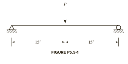
A W 10X 77 has continuous lateral support. The load P is a service live load and
Following is the given beam:

Calculation:
We have following properties for W 10X 77 from ASIC manual
| DesignationImperial (in x lb/ft) | Depth h (in) | Width w (in) | Web Thickness tw (in) | Flange Thickness tf (in) | Sectional Area (in2) | Weight (lbf/ft) | Static Parameters | ||||
| Moment of Inertia | Elastic Section Modulus | ||||||||||
| Ix (in4) | Iy (in4) | Sx (in3) | Sy (in3) | ||||||||
| W 10 x 77 | 10.60 | 10.190 | 0.530 | 0.870 | 22.6 | 77 | 455 | 154 | 85.9 | 30.1 | |
Let’s check for the compactness of the given W-shape beam using part
For Flange:
Where,
If the above condition satisfies, then the flange is non compact for flexure
Therefore, the web is compact.
Calculate the nominal flexural strength using the formula
Where,
Manual.
Now, calculate the maximum bending moment due to dead load, we have
Maximum bending moment for a simply supported beam carrying a dead UDL
Where,
Substitute,
Calculate the maximum bending moment for a simply supported beam carrying a concentrated
live load of the beam:
Where, P is the concentrated load and L is the length of the beam is.
Now, using Load Resistance and Factored design method:
Calculate the maximum permissible load P.
Substitute
Calculate P, by equating the maximum bending moment with the flexural strength of the beam;
Where,
Substitute
Conclusion:
Therefore, the maximum permissible load from LFRD method is
(b)
Maximum permissible load using ASD method.
Answer to Problem 5.5.1P
The maximum permissible load from ASD method is
Explanation of Solution
Given information:
A W 10X 77 has continuous lateral support. The load P is a service live load and
Calculation:
We have following properties for W 10X 77 from ASIC manual
| DesignationImperial (in x lb/ft) | Depthh (in) | Widthw (in) | Web Thicknesstw (in) | Flange Thicknesstf (in) | Sectional Area (in2) | Weight (lbf/ft) | Static Parameters | ||||
| Moment of Inertia | Elastic Section Modulus | ||||||||||
| Ix (in4) | Iy (in4) | Sx (in3) | Sy (in3) | ||||||||
| W 10 x 77 | 10.60 | 10.190 | 0.530 | 0.870 | 22.6 | 77 | 455 | 154 | 85.9 | 30.1 | |
Let’s check for the compactness of the given W-shape beam using part
For Flange:
Where,
If the above condition satisfies, then the flange is non compact for flexure
Therefore, the web is compact.
Calculate the nominal flexural strength using the formula
Now, calculate the maximum bending moment due to dead load, we have
Maximum bending moment for a simply supported beam carrying a dead UDL
Where,
Substitute,
Calculate the maximum bending moment for a simply supported beam carrying a concentrated
live load of the beam:
Where, P is the concentrated load and L is the length of the beam is.
Calculate the uniformly distributed load on the beam by equating
Allowable stress design method:
Substitute
Calculate P, by equating the maximum bending moment with the flexural strength of the beam:
Substitute,
Conclusion:
Therefore, the maximum permissible load from ASD method is
Want to see more full solutions like this?
Chapter 5 Solutions
STEEL DESIGN (LOOSELEAF)


- QI/ A beam carries the loads shown in figure, if the tensile stress must not exceed 20 MPa and the compression stress 70MPa. Find the maximum value of load P Som, r W=2-5p W/m - P Lflj Ko ; - 3,‘, ) o Jo 1 er -1 /i e,arrow_forwardUse A 992 Steel and Select the most economical W shape for the beam shown in the figure below. The beam weight is not included in the service loads shown. Do not check deflection. Assume continuous Lateral support. K 6 IPD = lok PL=20k * 161 1 WD= 3-33 K/F+ WL=6-67 k/Ft -xhularrow_forwardThe AD beam, which is fixed at left end, is under various loads as shown below. a) Draw internal load diagrams (Nx, Vy, M2) using the method of section. b) Determine the state of stress at points G, H and I for section B. c) For the corresponding points, indicate the results (i.e. stress components) on a differential element. b2 A B G М F2 2l h bi GIVEN DATA: Fo = 10000 N, F1 1200 N, F2 = 1000 N, qo = 50 N/cm, Mo = 50000 Nem, l = 25 cm bi = 10 cm, b2 = 20 cm, h 12 cm, t 1 cmarrow_forward
- ASAParrow_forwardHow much service live load, in kips per foot, can be supported? The member weight is the only dead load. The axial compressive load consists of a service dead load of 10 kips and a service live load of 20 kips. Do not consider moment amplification. Bending is about the x axis, and the steel is A992. a. Use LRFD. b. Use ASD.arrow_forwardThe rigid frame shown is unbraced. The members are oriented so that bending is about the strong axis. Support conditions in the direction perpendicular to the plane of the frame are such that Ky = 1.0. The beams are W410 x 85, and the columns are W250 × 89. A992 steel is used, Fy=345 mPa. The axial compressive dead load is 750 kN and the axial compressive live load is 900 kN. Use the AISC alignment chart or Magdy I. Salama Formula for Kx. 4.5 m 5.5 m 6.0 m ly Cw Sx mm^2 mm^4 mm^3 1100 1510 A Ix rx Sy ry Zx Zy SECTION m mm^4 mm^3 378 mm^3 mm^3 mm^3 mm^9 1040 713 716 mm mm W250x89 4500 11400 143 W410x85 5500 10800 315 48.4 65.2 1230 574 1730 310 112 171 18 199 40.8 926 Which of the following best gives the axial strength of column AB? Use the NSCP 2015 LRFD specifications. O 2,340 kN 1,647 kN O 2,745 kN O 2,471 kNarrow_forward
- For the given properties of beam below. Design the reinforcements of the beam. d'=75 mm b=400 mm d=580 mm fc'=35 MPa fy=320 MPa Mu=1000000000N mm Input is 0 in As' if compression bars are not needed. A. USE NSCP 2001, As = mm2, As' = mm2 B. USE NSCP 2015, As = mm2, As' = mm2 %3Darrow_forwardExample 8 The column shown in Figure is subjected to a service dead load of 140 kips and a service live load of 420 kips. Use A992 steel and select a W-shape. hing 20' 8' Support in strong direction Support in weak direction Solution KL 20 = 2.5 IIarrow_forwardThe rigid frame shown is unbraced. The members are oriented so that bending is about the strong axis. Support conditions in the direction perpendicular to the plane of the frame are such that Ky = 1.0. The beams are W410 x 85, and the columns are W250 × 89. A992 steel is used, Fy=345 mPa. The axial compressive dead load is 750 kN and the axial compressive live load is 900 kN. Use the AISC alignment chart or Magdy I. Salama Formula for Kx. B 4.5 m 5.5 m 6.0 m Sx mm^2 mm^4 mm^3 1100 L A Ix Sy Zx Cw ly mm mm^4 mm^3 112 48.4 Zy mm mm^3 mm^3 mm^3 mm19 1040 SECTION ry 65.2 1230 574 713 W250x89 4500 11400 W410x85 5500 10800 315 143 378 1510 171 18 199 40.8 1730 310 926 716 Which of the following best gives the allowable axial strength of column AB? Use the NSCP 2015 LRFD specifications. O 1,647 kN 2,471 kN O 900 kNarrow_forward
- The rigid frame shown is unbraced. The members are oriented so that bending is about the strong axis. Support conditions in the direction perpendicular to the plane of the frame are such that Ky = 1.0. The beams are W410 x 85, and the columns are W250 x 89. A992 steel is used, Fy=345 mPa. The axial compressive dead load is 750 kN and the axial compressive live load is 900 kN. Use the AISC alignment chart or Magdy I. Salama Formula for Kx. B 4.5 m 5.5 m 6.0 m Sx ly Sy mm^4 mm^3 A Ix Zx Zy J Cw rx ry mm^3 mm^3 mm^3 mm^g SECTION mm^2 mm^4 mm^3 mm mm W250x89 4500 W410x85 5500 10800 11400 143 1100 112 48.4 378 65.2 1230 574 1040 713 315 1510 171 18 199 40.8 1730 310 926 716 Which of the following best gives the allowable axial strength of column AB? Use the NSCP 2015 LRFD specifications. O 1,647 kN O 2,471 kN O 900 kNarrow_forwardDetermine the safe load of the column section shown, if it has a yield strength of 25 MPa. E = 200000 MPa. Use NSCP Specifications. Fyz248 mpa Properties of Channel Section d = 305 mm t₂ = 7.2 mm A = 3929 mm² t₁ = 12.7 mm Ix=53.7 x 10mm¹ x = 117 mm Properties of W 460 x 74 A = 9450 mm² b = 190 mm ly= 1.61 x 10 mm x = 17.7 mm tw = 9.0 mm rx = 188 mm ry = 41.9 mm d = 457 mm tr = 14.5 mm Ix = 333 x 10 mm Iy = 16.6 x 10mm* 7.21 When the height of column is 6 m. When the height of column is 10 m. Assume K= 1.0 457 CIVIL ENGINEERING- STEEL DESIGNarrow_forward2. The beam shown in Figure P5.8-3 is a W16 × 31 of A992 steel and has continuous lateral support. The two concentrated loads are service live loads. Neglect the weight of the beam and determine whether the beam is adequate for flexure and shear. a. Use LRFD. b. Use ASD.arrow_forward

 Structural Analysis (10th Edition)Civil EngineeringISBN:9780134610672Author:Russell C. HibbelerPublisher:PEARSON
 Principles of Foundation Engineering (MindTap Cou...Civil EngineeringISBN:9781337705028Author:Braja M. Das, Nagaratnam SivakuganPublisher:Cengage Learning
 Fundamentals of Structural AnalysisCivil EngineeringISBN:9780073398006Author:Kenneth M. Leet Emeritus, Chia-Ming Uang, Joel LanningPublisher:McGraw-Hill Education
 Traffic and Highway EngineeringCivil EngineeringISBN:9781305156241Author:Garber, Nicholas J.Publisher:Cengage Learning