
Programmable Logic Controllers
5th Edition
ISBN: 9780073373843
Author: Frank D. Petruzella
Publisher: McGraw-Hill Education
expand_more
expand_more
format_list_bulleted
Concept explainers
Question
Chapter 5, Problem 21RQ
Program Plan Intro
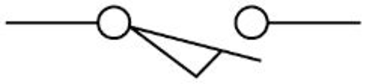
NO limit switch:
- Normally Open (NO) limit switch refers to a commonly used industrial control device.
- It is used to operate when a predetermined limit is reached.
- It is actuated by contact with an object such as a cam.
- An electrical symbol used to represent NO limit switch is given below
Solenoid:
- The working of solenoid is based on the principle of magnetic induction.
- It contains a coil, frame, and a plunger known as armature.
- The main function of solenoid is to convert electrical signals into
mechanical motion. - Due to its magnetic movement, solenoid is used in different areas such as locking of two devices, interlocking of gear wheel in automobiles and some other medical application.
Expert Solution & Answer
Want to see the full answer?
Check out a sample textbook solution
Students have asked these similar questions
module in slot 5 of the
2. Redraw the shown in Figure 5-55 corrected
program
to solve the problem of a nested contact.
56 cor-
1. Design the ladder logic for turning ON an output (OUT 1) when normally open pushbutton
(IN_1) and switch (IN_6) are closed. OUT 1 keeps on even when IN 1 gets released. Add an
additional normally open momentary pushbutton IN 2 that resets OUT_1 when it is pressed.
When pushbutton IN 2 is pressed momentarily, output OUT_1 will remain OFF unless IN 1 and
IN 6 are again closed together.
Purpose:
The entry/Exit of the parking lot is a single lane passage. By controlling the indicators, the program ensures that only one car can pass
through the Entry/Exit so as to prevent car accident between entering and leaving cars.
Y1
X1
Program Description:
In the parking lot, there are two light indicators individually directing the entering and leaving cars. By the interlock control circuit, only
one indicator will show "GO" signal and the car accident will thus be prevented.
When an
the same time, the leaving car indicator will show "STOP". Car entering is allowed but leaving is prohibited in this case.
When a leaving car draws near the vehicle control barrier, X1 will be ON and so will Y1. The leaving car indicator will show "GO" and the
entering car indicator will show "STOP"|
draws near the vehicle control barrier, XO will be ON and so will YO. The entering car indicator will show "GO". At
TOP
GO
Chapter 5 Solutions
Programmable Logic Controllers
Ch. 5 - What does the memory map for a typical PLC...Ch. 5 - Compare the function of the PLC program and data...Ch. 5 - Prob. 3RQCh. 5 - Prob. 4RQCh. 5 - a. What information is stored in the input image...Ch. 5 - a. What information is stored in the output image...Ch. 5 - Prob. 7RQCh. 5 - List four factors that enter into the length of...Ch. 5 - Prob. 9RQCh. 5 - Prob. 10RQ
Ch. 5 - Prob. 11RQCh. 5 - Answer the following with regard to the Examine If...Ch. 5 - Answer the following with regard to the Examine If...Ch. 5 - Answer the following with regard to the Output...Ch. 5 - A normally closed pushbutton is connected to a PLC...Ch. 5 - Prob. 16RQCh. 5 - Prob. 17RQCh. 5 - Prob. 18RQCh. 5 - Prob. 19RQCh. 5 - Prob. 20RQCh. 5 - Prob. 21RQCh. 5 - Explain the purpose of Windows based programming...Ch. 5 - Prob. 23RQCh. 5 - Prob. 24RQCh. 5 - Prob. 25RQCh. 5 - Prob. 26RQCh. 5 - Assign each of the following discrete input and...Ch. 5 - Prob. 2PCh. 5 - Prob. 3PCh. 5 - Redraw the program shown in Figure 5-57 corrected...Ch. 5 - Redraw the program shown in Figure 5-58 corrected...Ch. 5 - Prob. 6PCh. 5 - Prob. 7PCh. 5 - Prob. 8PCh. 5 - Write the ladder logic program needed to implement...
Knowledge Booster


Learn more about
Need a deep-dive on the concept behind this application? Look no further. Learn more about this topic, computer-science and related others by exploring similar questions and additional content below.Similar questions
- PLEASE USE METER_PIN INPUT VALUES IMPLEMENT A TIMER BASED ON THE VALUE IN THE METERarrow_forwardArduino programming exercises using Uno Microcontroller Write a program that starts by having a red LED attached to pin 8 go on. The LED will stay on until a button is pressed. A half second after the button is pressed, the red LED will go off and a green LED will go on for 5 seconds. After this the whole cycle repeats.arrow_forwardmodule full_adder(input a, input b, input cin, output sum, output cout);wire s1, c1, c2;xor(sum, a, b);and(c1, a, b);and(c2, sum, cin);or(cout, c1, c2);endmodule module fulladd16_gate(input [15:0] a, input [15:0] b, input cin, output [16:0] sum, output reg cout);wire [15:0] carry;full_adder fa0(a[0], b[0], cin, sum[0], carry[0]);full_adder fa1(a[1], b[1], carry[0], sum[1], carry[1]);full_adder fa2(a[2], b[2], carry[1], sum[2], carry[2]);full_adder fa3(a[3], b[3], carry[2], sum[3], carry[3]);full_adder fa4(a[4], b[4], carry[3], sum[4], carry[4]);full_adder fa5(a[5], b[5], carry[4], sum[5], carry[5]);full_adder fa6(a[6], b[6], carry[5], sum[6], carry[6]);full_adder fa7(a[7], b[7], carry[6], sum[7], carry[7]);full_adder fa8(a[8], b[8], carry[7], sum[8], carry[8]);full_adder fa9(a[9], b[9], carry[8], sum[9], carry[9]);full_adder fa10(a[10], b[10], carry[9], sum[10], carry[10]);full_adder fa11(a[11], b[11], carry[10], sum[11], carry[11]);full_adder fa12(a[12], b[12], carry[11], sum[12],…arrow_forward
- Describe counter controlled while loops.arrow_forwardArduino programming exercises using Uno Microcontroller Write a program that starts out by flashing an LED connected to pin7 at 2Hz. On a button press (button is attached to pin4 – wire active low), the LED turns on for 2 seconds. After this the whole cycle repeats.arrow_forward.............Control loop is a continuous cycle of the PLC reading Ladder Logic O Outputs Inputs Oarrow_forward
- The input waveform shown in the figure below is applied to an inverter, which is used to operate a light on a control circuit. Draw the timing diagram of the output waveform in proper relation to the input. VIN HIGH LOW urrarrow_forward) In an open-loop control system: (a) System variables effect the output signal (b) Output signal has no control on the input signal (c) None of the variables have any effect on the input signal (d) None of thesearrow_forward8 Controller considers as Synchronous Sequential circuit. False Truearrow_forward
arrow_back_ios
SEE MORE QUESTIONS
arrow_forward_ios
Recommended textbooks for you
 Database System ConceptsComputer ScienceISBN:9780078022159Author:Abraham Silberschatz Professor, Henry F. Korth, S. SudarshanPublisher:McGraw-Hill Education
 Starting Out with Python (4th Edition)Computer ScienceISBN:9780134444321Author:Tony GaddisPublisher:PEARSON
 Digital Fundamentals (11th Edition)Computer ScienceISBN:9780132737968Author:Thomas L. FloydPublisher:PEARSON
 C How to Program (8th Edition)Computer ScienceISBN:9780133976892Author:Paul J. Deitel, Harvey DeitelPublisher:PEARSON
 Database Systems: Design, Implementation, & Manag...Computer ScienceISBN:9781337627900Author:Carlos Coronel, Steven MorrisPublisher:Cengage Learning
 Programmable Logic ControllersComputer ScienceISBN:9780073373843Author:Frank D. PetruzellaPublisher:McGraw-Hill Education
Database System Concepts
Computer Science
ISBN:9780078022159
Author:Abraham Silberschatz Professor, Henry F. Korth, S. Sudarshan
Publisher:McGraw-Hill Education
Starting Out with Python (4th Edition)
Computer Science
ISBN:9780134444321
Author:Tony Gaddis
Publisher:PEARSON
Digital Fundamentals (11th Edition)
Computer Science
ISBN:9780132737968
Author:Thomas L. Floyd
Publisher:PEARSON
C How to Program (8th Edition)
Computer Science
ISBN:9780133976892
Author:Paul J. Deitel, Harvey Deitel
Publisher:PEARSON
Database Systems: Design, Implementation, & Manag...
Computer Science
ISBN:9781337627900
Author:Carlos Coronel, Steven Morris
Publisher:Cengage Learning
Programmable Logic Controllers
Computer Science
ISBN:9780073373843
Author:Frank D. Petruzella
Publisher:McGraw-Hill Education