
Programmable Logic Controllers
5th Edition
ISBN: 9780073373843
Author: Frank D. Petruzella
Publisher: McGraw-Hill Education
expand_more
expand_more
format_list_bulleted
Videos
Textbook Question
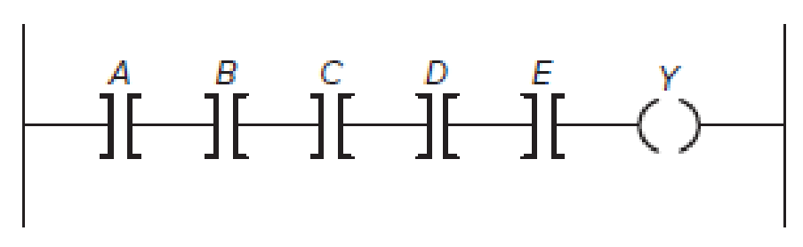
Chapter 5, Problem 5P
Redraw the
Expert Solution & Answer
Want to see the full answer?
Check out a sample textbook solution
Students have asked these similar questions
Draw the transistor level of the following function
Q2:
For the circuit shown in below, use (matlab, c++, or python) and Nodal Analysis to:
a) Find the voltage across the current source 11 terminals
b)
Find the current through the resistance R1
c)
Find the real and reactive Powers delivered by the current source 11
Find the real and reactive Powers consumed by the capacitor C2
d)
11
10 A RMS
50 Hz
+35 Deg
Z1
AM
R2 402
Z4
R4 80
m
Z2
L2 15 mH
12 7A RMS 50 Hz +74 Deg
Zc1
C1 150 F
R3 30
www
w
R6 40
Z6
L3 25 mH
E1 100 V RMS
- 40 Deg
Z5 50 Hz
www
R5 20
Zc2
C2 200 F
Ex4: Design a counter with 7 flip-flops that goes through the following binary repeated
sequence: 0, 1, 3, 7, 6, 4. Show that when binary states 010 and 101 are considered as
don't care conditions, the counter may not operate properly. Find a way to correct the
design with don't care
and without
don't care
The number of flip-flops required is three.
• Table below shows the desired circuit excitation table.
Present Next
Flip-flop inputs
state state
ABC ABC TA TB
C
000
001 0
0
1
001
011 0
1
0
010
XXX
X
X
X
011
111
1
1
0
100 000
1
1
0
101 XXX
X
X
X
110
100
0
1
0
111
110 0 0 1
Chapter 5 Solutions
Programmable Logic Controllers
Ch. 5 - What does the memory map for a typical PLC...Ch. 5 - Compare the function of the PLC program and data...Ch. 5 - Prob. 3RQCh. 5 - Prob. 4RQCh. 5 - a. What information is stored in the input image...Ch. 5 - a. What information is stored in the output image...Ch. 5 - Prob. 7RQCh. 5 - List four factors that enter into the length of...Ch. 5 - Prob. 9RQCh. 5 - Prob. 10RQ
Ch. 5 - Prob. 11RQCh. 5 - Answer the following with regard to the Examine If...Ch. 5 - Answer the following with regard to the Examine If...Ch. 5 - Answer the following with regard to the Output...Ch. 5 - A normally closed pushbutton is connected to a PLC...Ch. 5 - Prob. 16RQCh. 5 - Prob. 17RQCh. 5 - Prob. 18RQCh. 5 - Prob. 19RQCh. 5 - Prob. 20RQCh. 5 - Prob. 21RQCh. 5 - Explain the purpose of Windows based programming...Ch. 5 - Prob. 23RQCh. 5 - Prob. 24RQCh. 5 - Prob. 25RQCh. 5 - Prob. 26RQCh. 5 - Assign each of the following discrete input and...Ch. 5 - Prob. 2PCh. 5 - Prob. 3PCh. 5 - Redraw the program shown in Figure 5-57 corrected...Ch. 5 - Redraw the program shown in Figure 5-58 corrected...Ch. 5 - Prob. 6PCh. 5 - Prob. 7PCh. 5 - Prob. 8PCh. 5 - Write the ladder logic program needed to implement...
Knowledge Booster


Learn more about
Need a deep-dive on the concept behind this application? Look no further. Learn more about this topic, computer-science and related others by exploring similar questions and additional content below.Similar questions
- please also draw the line for clock signal.arrow_forwardDesign a combinational circuit with four inputs, w, x, y, and z, and four outputs, A, B, C and D. When the binary input is 0, 1, 2, 3, 4,5,6 the binary output is two greater than the input. When the binary input is 7,8, 9, 10, 12,13,14,15 the binary output is three less than the input.a) Derive the Boolean expressions for four outputs A, B, C and D.. Evaluate the outputs as a function of the four inputs.(b) List the truth table with 16 binary combinations of the four input variables w, x, y, and z.(c) Draw the logic gate circuit.(d) Write Gate Level HDL code for the corresponding to the logic gate circuit.arrow_forwardDesign of ALU control circuit for maximum 4 input variables (Ainvert, Binvert , F1 and F0) using QMM((please use ""QMM"" its mandatory))arrow_forward
- Design 4 to 1 mutiplexer using the design procedurearrow_forwardDesign Problem: Using the 74163 and any necessary logic, design a counter that counts continuously in the following sequence: 0 to 32 skipping 13 then repeats. Discussion: • Modify the counter such that it can be count to 63. Discuss your experience in the laboratory and any problems with the procedure. Show the circuit for the design problem only. Include in your report. Make sure to include the pin numbers of the gates used. You do NOT have to show the package outline, just the pin numbers of the gates.arrow_forwardProblem 2: You are to design and simulate a sequential circuit which has two inputs, X and an enable input, E. You will be using two JK Flip-Flops in your design. The following is the requirements for your design: When the circuit is disabled, i.e., E = 0: There will be no change, that is, the circuit remains in the same state regardless of the value of X. When the circuit is enabled, i.e., = 1: If X = 1, the circuit goes through circular state transitions, 00 > 01 → 10 → 11 → 00 and repeats, If X = 0, the circuit goes through circular state transitions, 00 > 11 → 10 → 01 → 00 and repeats,arrow_forward
- ->Simplify the Boolean function and design its logic gates(NAND and NOR). F1(x,y,z) = xy’z+xyz+y’z’ NOTE: Using NAND and NOR GATES & Handwritten form (NEAT).arrow_forwardDesign circuit that has an input w and an output z. The circuit is a sequence detector that produces z = 1 when the previous two values of w were 00 or 11; otherwise z = 0. Use W=0101100010101110101011100010 a) For this problem design the circuit using JK flipflops, draw the state diagram, true table, logic circuit.b) Do the same that as part A but this time use D flipflops: draw the state diagram, true table, logic circuit.arrow_forward• Design a sequential circuit with two T Flip Flops, A and B, and two inputs, E and x. If E=0, the circuit remains in the same state regardless of the value of x. When E=1 and x=1, the circuit goes through the state transitions from 00 to 01 to 10 to 11 back to 00, and repeats. When E=1 and x=0, the circuit goes through the state transition from 00 to 11 to 10 to 01 back to 00, and repeatsarrow_forward
- = 0, Design a sequential circuit with two D flip-flops A and B, and one input x_in. When x_in the state of the circuit remains the same. When x in = 1, the circuit goes through the state transitions from 00 to 01, to 11, to 10, back to 00, and repeats.arrow_forwardDesign a combinational circuit with four inputs, w, x, y, and z, and four outputs, A, B, C and D. When the binary input is 0, 1, 2, 3, 4,5,6 the binary output is two greater than the input. When the binary input is 7,8, 9, 10, 12,13,14,15 the binary output is three less than the input.arrow_forward2. Design a combinational circuit with three inputs, x, y, and z, and three outputs, A, B, and C. When the binary input represents any of the decimal digits 1, 2, 3, or 6, the binary output should represent the decimal digit that is one greater than the input, that is 2, 3, 4 and 7, respectively. Similarly, when the binary input represents any of the digits 4, or 7, the binary output should represent the digit that is two less than the input. The remaining two inputs, that are the binary representations of the decimal digits 0 and 5 never occur. Draw the truth table, and give all the minimal forms for the functions that represent the outputs A, B, and C. Uarrow_forward
arrow_back_ios
SEE MORE QUESTIONS
arrow_forward_ios
Recommended textbooks for you
 Database System ConceptsComputer ScienceISBN:9780078022159Author:Abraham Silberschatz Professor, Henry F. Korth, S. SudarshanPublisher:McGraw-Hill Education
 Starting Out with Python (4th Edition)Computer ScienceISBN:9780134444321Author:Tony GaddisPublisher:PEARSON
 Digital Fundamentals (11th Edition)Computer ScienceISBN:9780132737968Author:Thomas L. FloydPublisher:PEARSON
 C How to Program (8th Edition)Computer ScienceISBN:9780133976892Author:Paul J. Deitel, Harvey DeitelPublisher:PEARSON
 Database Systems: Design, Implementation, & Manag...Computer ScienceISBN:9781337627900Author:Carlos Coronel, Steven MorrisPublisher:Cengage Learning
 Programmable Logic ControllersComputer ScienceISBN:9780073373843Author:Frank D. PetruzellaPublisher:McGraw-Hill Education
Database System Concepts
Computer Science
ISBN:9780078022159
Author:Abraham Silberschatz Professor, Henry F. Korth, S. Sudarshan
Publisher:McGraw-Hill Education
Starting Out with Python (4th Edition)
Computer Science
ISBN:9780134444321
Author:Tony Gaddis
Publisher:PEARSON
Digital Fundamentals (11th Edition)
Computer Science
ISBN:9780132737968
Author:Thomas L. Floyd
Publisher:PEARSON
C How to Program (8th Edition)
Computer Science
ISBN:9780133976892
Author:Paul J. Deitel, Harvey Deitel
Publisher:PEARSON
Database Systems: Design, Implementation, & Manag...
Computer Science
ISBN:9781337627900
Author:Carlos Coronel, Steven Morris
Publisher:Cengage Learning
Programmable Logic Controllers
Computer Science
ISBN:9780073373843
Author:Frank D. Petruzella
Publisher:McGraw-Hill Education
Pressure Sensors with Display; Author: Balluff Worldwide;https://www.youtube.com/watch?v=HqAV2xjCLxE;License: Standard Youtube License