What is motor control wiring?
Motor control wiring refers to the wiring of various components of a motor and links it to the controller. The wiring diagram shows the connection points of wires to all the components and the main circuit. The motor control wirings can also be represented with the help of line diagrams. Line diagrams are also known as schematic diagrams or elementary diagrams. The line diagrams show the basic operational circuit of motor control. The control circuit is a type of circuit that has a very low voltage or low current which controls large voltage and currents that supply power to the devices and equipment. The single-phase and three-phase AC squirrel cage induction motors require some type of control circuit to initiate a start function or a stop function.
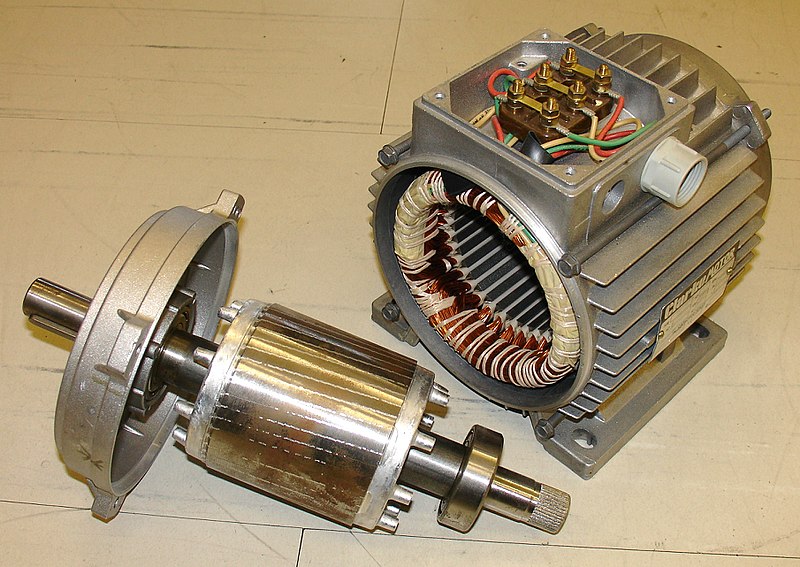
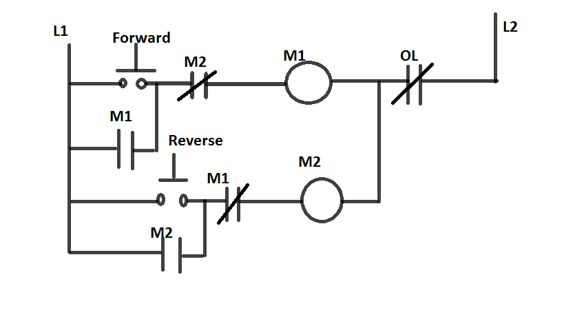
There are two types of control circuits which are two-wire control circuits and three-wire control circuits. To control the magnetic motor starter, the two-wire control uses maintained contact devices and the three-wire control uses momentary contact devices to control the magnetic motor starter. Figure 1 shows an electric motor rotor and stator part and figure 2 shows an electric motor control circuit.
Motor control wiring methods
To operate safely and efficiently, an electric motor must have a method of control. The control circuit of the motor varies from simple to complex. Using manual controls, magnetic controls, motor drives, or PLCs (Programmable Logic Controller) to control the operation of the motor, the no reversing motor control circuits can be wired similar to reversing motor control circuits. Different methods of wiring a motor and motor control circuit are present. Individually or in combination to control the operation of a motor, these methods can be used. There are many advantages and disadvantages of the motor control wiring method. The four basic types of motor control wiring are- direct hardwiring, hardwiring using terminal strips, programmable logic controller wiring, or PLC (it can be either programmed to control motor automatically or by manually using pushbuttons), and electric motor drive wiring.
Direct hardwiring
This is the oldest and straightforward motor control wiring method. Here, the power circuit and the control circuit are wired point-to-point. When each component of the wiring is connected to the next component directly, it is called point-to-point wiring. For instance, terminal 1 of the transformer is connected directly to the fuse and the fuse, in turn, is connected to the stop pushbutton directly, whereas the stop pushbutton is connected directly to the reverse pushbutton and this reverse pushbutton is connected directly to the forward pushbutton and it continues so on until the final connection from the contact of overload is made back to the transformer terminal 2. For a while, a direct hardwired circuit may operate properly.
The circuit troubleshooting and the circuit modification are time-consuming and this is the disadvantage of a direct hardwired circuit. The circuit operations are first understood, the measurements are taken and the problem is identified when a problem occurs in a direct hardwired circuit. For instance, by tracing each wire throughout the circuit, the circuit wiring can be determined without a wiring diagram. The problem in the circuit can be eventually found but it is time-consuming to trace each wire in a circuit to find the wire with a problem. By gaining experience and by working on a circuit several times and also by understanding its components and operations, the time is saved.
Hardwiring using terminal strips
The easy circuit modification is allowed by hardwiring to a terminal strip and simplifies circuit troubleshooting. On the line diagram, each wire in the control circuit is assigned a point of reference to identify the different wires that connect the components in the circuit when wiring using a terminal strip is done. Each point of reference is assigned a wire reference number.
PLC motor wiring
When the start button is pressed, a PLC has to start a motor. Three interlocks are present in it which are motor vibration high, overload, and the motor temperature high. The PLC has to stop the motor immediately when the interlock is activated. If the stop button is also pressed then the PLC has to stop the motor. The inputs of PLC are, start pushbutton, stop pushbutton, vibration high, temperature high, overload relay trip, run feedback, and local/remote status. The outputs of PLC are, start command, stop command, and start permissive. In PLC, latched is the word used when the output must be activated even after the entry stops. The latching is used to keep the motor running until and unless the pushbutton is pressed once again. The PLC normally works on a voltage of 12 or 24 volts DC supply.
Electric motor drive wiring
Digital inputs and outputs are linked to an electric motor drive with separate single conductors. Analog inputs and outputs are merged to an electric motor drive with a pair of twisted shielded cables. Certain precautions include control and power wiring attached separately, avoiding any merging of AC and DC controls within the same unit, and in unavoidable circumstances wherein the control and power cross, they should be strictly crossed at 90° angles.
Troubleshooting the motor circuit
To help isolate the problems, the technician can go directly to the terminal strip and take measurements when troubleshooting a circuit with a terminal strip. On the terminals, the DMM is first placed. The problem is located on the primary side of the transformer if the voltage is not correct at that point. One DMM lead is left on one terminal and the other lead is moved to a different terminal if the voltage is correct at both the terminals until the problem is located.
Motor wiring diagrams
The conductive connections between electrical apparatus are shown in the wiring diagrams. The internal or external connections are shown by them but in general, they do not give any information related to the operation mode. Wiring tables can be used instead of wiring diagrams.
- Unit wiring diagram: It represents all the connections with the device or the device combinations.
- Interconnection diagram: It represents the connection between the device or device combinations within an installation.
- Terminal diagram: It represents the connection of points of an electrical installation and the external and internal conductive connections which are connected to them.
- Location diagram: It represents the physical position of the apparatus and it needs not be scaled. In this diagram, we can find the marking of electrical apparatus as well as designs.
Use of relay in motor control applications
In industries and process control, many motor applications require relays as critical control elements. In a circuit, relays are used as a primary switching device. An electromechanical relay is a type that is operated with the help of an electromagnet. By energizing an electromagnet, the relay turns the load circuit ON or OFF. In a relay, a selector switch can control the ON or OFF of different types of the current circuit just by rotating the handle. In motor contactors and starters, the electromechanical relay is often used. A relay may have a number of different contacts but has only one coil. The relay coil is energized due to the overcurrent in the system.
The electromechanical relay contains both stationary coil and moving coil. The moving contacts are referred to as normally open or normally closed. An electromagnetic field is produced when the relay coils are energized and the action of this field causes the armature to move by closing the normally-open contacts and opening the normally-closed contacts. More than one set of contacts can be actuated by one relay coil assembly.
Thermal or electric relays are the two types of overload relays. These overload relays are used in several applications to protect the motor from getting damaged and to provide overload protection.
Context and Applications
This topic is significant in the professional exam for graduate and postgraduate courses.
- Bachelors in Electrical Engineering
- Masters in Electrical Engineering
Practice Problems
Q1. What does a line diagram show?
- Basic operation of motor
- Complex operation of motor
- Connections of motor
- None of these
Answer: Option a
Explanation: The line diagrams show the basic operational circuit of motor control.
Q2. Which of the following is/are motor control wiring method(s)?
- Direct hardwiring
- Hardwiring using terminal strips
- PLC wiring
- All of the above
Answer: Option d
Explanation: The four basic types of motor control wiring are- direct hardwiring, hardwiring using terminal strips, PLC wiring, and electric motor drive wiring.
Q3. Which circuit(s) is/are wired in direct hardwiring?
- Power circuit
- Control circuit
- Both a and b
- None of these
Answer: Option c
Explanation: The power circuit and the control circuit are wired point-to-point in the direct hardwiring control method.
Q4. Which wiring diagram represents all the connections of the device and device combinations?
- Unit wiring diagram
- Interconnection diagram
- Terminal diagram
- Location diagram
Answer: Option a
Explanation: The unit wiring diagram represents all the connections with the device or the device combinations.
Q5. Which diagram represents the physical position of an apparatus?
- Unit wiring diagram
- Interconnection diagram
- Terminal diagram
- Location diagram
Answer: Option d
Explanation: The location diagram represents the physical position of the apparatus and it needs not be scaled.
Related Concepts
- Motor control center (MCC)
Want more help with your electrical engineering homework?
*Response times may vary by subject and question complexity. Median response time is 34 minutes for paid subscribers and may be longer for promotional offers.
Search. Solve. Succeed!
Study smarter access to millions of step-by step textbook solutions, our Q&A library, and AI powered Math Solver. Plus, you get 30 questions to ask an expert each month.
Motor Control Wiring Method Homework Questions from Fellow Students
Browse our recently answered Motor Control Wiring Method homework questions.
Search. Solve. Succeed!
Study smarter access to millions of step-by step textbook solutions, our Q&A library, and AI powered Math Solver. Plus, you get 30 questions to ask an expert each month.