
Mechanics of Materials
11th Edition
ISBN: 9780137605460
Author: Russell C. Hibbeler
Publisher: Pearson Education (US)
expand_more
expand_more
format_list_bulleted
Concept explainers
Videos
Textbook Question
Chapter 4.5, Problem 57P
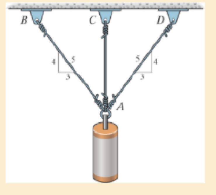
The A-36 steel wires AB and AD each have a diameter of 2 mm and unloaded lengths of each wire are LAC = 1.60 m and LAB = LAD = 2.00 m. Determine the required diameter of wire AC so that each wire is subjected to the same force when the 150-kg mass is suspended from the ring at A.
Expert Solution & Answer
Want to see the full answer?
Check out a sample textbook solution
Students have asked these similar questions
The A-36 steel wires AB and AD each have a diameter of 2 mm and the unloaded lengths of each wire are LAC = 1.60 m and LAB = LAD = 2.00 m. Determine the required diameter of wire AC so that each wire is subjectedto the same force when the 150-kg mass is suspended from the ring at A.
ck C rests on the uniform 15-lb bar AB. The cable conne
ey at D. Find the magnitude of the force acting between t
30
-2 ft+
-6 ft-
C.
Determine the magnitude of the pin force at A.
Assume W = 830 lb, a = 5.5 ft, b = 4.0 ft, r = 8 in.
r
W
с
Answer: A = i
a
B
a
A
D
lb
b
Chapter 4 Solutions
Mechanics of Materials
Ch. 4.2 - The 20-mm-diameter A-36 steel rod is subjected to...Ch. 4.2 - Segments AB and CD of the assembly are solid...Ch. 4.2 - The 30-mm-diameter A992 steel rod is subjected to...Ch. 4.2 - If the 20-mm-diameter rod is made of A-36 steel...Ch. 4.2 - The 20-mm-diameter 2014-T6 aluminum rod is...Ch. 4.2 - The 20-mm-diameter 2014-T6 aluminum rod is...Ch. 4.2 - The copper shaft is subjected to the axial loads...Ch. 4.2 - The A-36 steel rod is subjected to the loading...Ch. 4.2 - The A-36 steel rod is subjected to the loading...Ch. 4.2 - The A-36 steel drill shaft of an oil well extends...
Ch. 4.2 - Prob. 8PCh. 4.2 - The post is made of Douglas fir and has a diameter...Ch. 4.2 - The post is made of Douglas fir and has a diameter...Ch. 4.2 - The coupling rod is subjected to a force of 5 kip....Ch. 4.2 - The pipe is stuck in the ground so that when it is...Ch. 4.2 - The assembly consists of three titanium...Ch. 4.2 - The assembly consists of two rigid bars that are...Ch. 4.2 - The truss consists of three members, each made...Ch. 4.2 - Solve Prob. 426 when the load P acts vertically...Ch. 4.2 - The ball is truncated at its ends and is used to...Ch. 4.5 - The column is constructed from high-strength...Ch. 4.5 - The column is constructed from high-strength...Ch. 4.5 - The A-36 steel pipe has a 6061-T6 aluminum core....Ch. 4.5 - The 304 stainless steel post A has a diameter of...Ch. 4.5 - The 304 stainless steel post A is surrounded by a...Ch. 4.5 - The 10-mm-diameter steel bolt is surrounded by a...Ch. 4.5 - The rigid beam is supported by the three suspender...Ch. 4.5 - The bolt AB has a diameter of 20 mm and passes...Ch. 4.5 - If the gap between C and the rigid wall at D is...Ch. 4.5 - The support consists of a solid red brass C83400...Ch. 4.5 - Prob. 55PCh. 4.5 - The three A-36 steel wires each have a diameter of...Ch. 4.5 - The A-36 steel wires AB and AD each have a...Ch. 4.5 - The assembly consists of two posts AB and CD each...Ch. 4.5 - The assembly consists of two posts AB and CD each...Ch. 4.5 - The assembly consists of two posts AB and CD each...Ch. 4.5 - The wheel is subjected to a force of 18 kN from...Ch. 4.6 - The C83400-red-brass rod AB and 2014-T6- aluminum...Ch. 4.6 - The assembly has the diameters and material...Ch. 4.6 - Prob. 72PCh. 4.6 - Prob. 77PCh. 4.6 - Prob. 80PCh. 4.6 - The 50-mm-diameter cylinder is made from Am...Ch. 4.6 - The 50-mm-diameter cylinder is made from Am...Ch. 4.6 - The metal strap has a thickness t and width w and...Ch. 4.9 - Determine the maximum normal stress developed in...Ch. 4.9 - If the allowable normal stress for the bar is...Ch. 4.9 - Prob. 89PCh. 4.9 - The A-36 steel plate has a thickness of 12 mm. If...Ch. 4.9 - Determine the maximum axial force P that can be...Ch. 4.9 - Determine the maximum normal stress developed in...Ch. 4.9 - The member is to be made from a steel plate that...Ch. 4.9 - Prob. 96PCh. 4.9 - The bar has a cross-sectional area of 0.5 in2 and...Ch. 4.9 - The distributed loading is applied to the rigid...Ch. 4.9 - The distributed loading is applied to the rigid...Ch. 4.9 - The rigid lever arm is supported by two A-36 steel...Ch. 4.9 - The rigid lever arm is supported by two A-36 steel...Ch. 4.9 - The wire BC has a diameter of 0.125 in. and the...Ch. 4.9 - Prob. 104PCh. 4.9 - Prob. 106PCh. 4 - The assembly consists of two A992 steel bolts AB...Ch. 4 - The assembly shown consists of two A992 steel...Ch. 4 - The rods each have the same 25-mm diameter and...Ch. 4 - Two A992 steel pipes, each having a...Ch. 4 - The force P is applied to the bar, which is made...Ch. 4 - The 2014-T6 aluminum rod has a diameter of 0.5 in....Ch. 4 - The 2014-T6 aluminum rod has a diameter of 0.5 in....Ch. 4 - The rigid link is supported by a pin at A and two...Ch. 4 - The joint is made from three A992 steel plates...
Knowledge Booster


Learn more about
Need a deep-dive on the concept behind this application? Look no further. Learn more about this topic, mechanical-engineering and related others by exploring similar questions and additional content below.Similar questions
- The bracket is held to the wall using three A-36 steel bolts at B, C, and D. Each bolt has a diameter of 0.5 in. and an unstretched length of 2 in. If a force of 800 lb is placed on the bracket as shown,determine the force developed in each bolt. For the calculation, assume that the bolts carry no shear; rather, the vertical force of 800 lb is supported by the toe at A. Also, assume that the wall and bracket are rigid. A greatly exaggerated deformation of the bolts is shown.arrow_forwardThe bracket is held to the wall using three A-36 steel bolts at B, C, and D. Each bolt has a diameter of 0.5 in. and an unstretched length of 2 in. If a force of 800 lb is placed on the bracket as shown, determine the force developed in each bolt. For the calculation, assume that the bolts carry no shear; rather, the vertical force of 800 lb is supported by the toe at A. Also, assume that the wall and bracket are rigid. A greatly exaggerated deformation of the bolts is shown.arrow_forwardDetermine the magnitude of the pin force at A.Assume W = 665 lb, a = 3.7 ft, b = 2.9 ft, r = 8 in.arrow_forward
- The oven door is spring loaded at C and pinned at A. Determine the magnitude of the normal force at section a-a that lies just to the right of C if W = 24.6 lb and 0 = 32°. B 8 in. O 20.9 lb O 21.7 lb O 18.6 lb O 19.3 lb O 22.4 lb 10 in.- 5 in. 12 in.arrow_forwardThe bracket is held to the wall using three A-36 steel bolts at B, C, and D. Each bolt has a diameter of 0.5 in. and an unstretched length of 2 in. If a force of 800 lb is placed on the bracket as shown, determine how far, s, the top bracket at bolt D moves away from the wall. For the calculation, assume that the bolts carry no shear; rather, the vertical force of 800 lb is supported by the toe at A. Also, assume that the wall and bracket are rigid. A greatly exaggerated deformation of the bolts is shown.arrow_forwardProblem 3: If the springs shown each have an unstretched length of 48 inches, determine the angle for equlibrium with the 10- lb lamp fixture. 4 ft www. k = 5 lb/ft 4 ft 0 wwwww k = 5 lb/ftarrow_forward
- 5 - The ring supports the 1000-N load and is held in position by the two cables attached to vertical walls . Find the tensions T1 and T2 by at least two different ways . 1C00 Narrow_forwardDetermine the magnitude of the pin force at A. Assume W = 750 lb, a = 2.7 ft, b = 2.0 ft, r = 6 in. a a r B A C W Answer: A = i D lb barrow_forwardThe collar C is fixed to rod AB using a glued bond that allows a maximum force of 405 N parallel to the axis of the rod. The collar has weight W acting in the negative z direction. Determine the weight W in N of the collar that will cause the glued bond to break as shown in figure.arrow_forward
- The three A-36 steel wires each have a diameter of 2 mm and unloaded lengths of LAC = 1.60 m and LAB = LAD = 2.00 m. Determine the force in each wire after the 150-kg mass is suspended from the ring at A.arrow_forwardQ5/ Three cables are joined at the junction ring C. Determine the tensions in cables AC and BC caused by the weight of the 30-kg cylinder. A 45° 15° 30% 30 kgarrow_forward3/15 Three cables are joined at the junction ring C. Deter- mine the tensions in cables AC and BC caused by the weight of the 30-kgkylinder. 45 15° 30 30 kg cylinderarrow_forward
arrow_back_ios
SEE MORE QUESTIONS
arrow_forward_ios
Recommended textbooks for you
 Elements Of ElectromagneticsMechanical EngineeringISBN:9780190698614Author:Sadiku, Matthew N. O.Publisher:Oxford University Press
 Mechanics of Materials (10th Edition)Mechanical EngineeringISBN:9780134319650Author:Russell C. HibbelerPublisher:PEARSON
 Thermodynamics: An Engineering ApproachMechanical EngineeringISBN:9781259822674Author:Yunus A. Cengel Dr., Michael A. BolesPublisher:McGraw-Hill Education
 Control Systems EngineeringMechanical EngineeringISBN:9781118170519Author:Norman S. NisePublisher:WILEY
 Mechanics of Materials (MindTap Course List)Mechanical EngineeringISBN:9781337093347Author:Barry J. Goodno, James M. GerePublisher:Cengage Learning
 Engineering Mechanics: StaticsMechanical EngineeringISBN:9781118807330Author:James L. Meriam, L. G. Kraige, J. N. BoltonPublisher:WILEY
Elements Of Electromagnetics
Mechanical Engineering
ISBN:9780190698614
Author:Sadiku, Matthew N. O.
Publisher:Oxford University Press
Mechanics of Materials (10th Edition)
Mechanical Engineering
ISBN:9780134319650
Author:Russell C. Hibbeler
Publisher:PEARSON
Thermodynamics: An Engineering Approach
Mechanical Engineering
ISBN:9781259822674
Author:Yunus A. Cengel Dr., Michael A. Boles
Publisher:McGraw-Hill Education
Control Systems Engineering
Mechanical Engineering
ISBN:9781118170519
Author:Norman S. Nise
Publisher:WILEY
Mechanics of Materials (MindTap Course List)
Mechanical Engineering
ISBN:9781337093347
Author:Barry J. Goodno, James M. Gere
Publisher:Cengage Learning
Engineering Mechanics: Statics
Mechanical Engineering
ISBN:9781118807330
Author:James L. Meriam, L. G. Kraige, J. N. Bolton
Publisher:WILEY
EVERYTHING on Axial Loading Normal Stress in 10 MINUTES - Mechanics of Materials; Author: Less Boring Lectures;https://www.youtube.com/watch?v=jQ-fNqZWrNg;License: Standard YouTube License, CC-BY