
Concept explainers
Videos
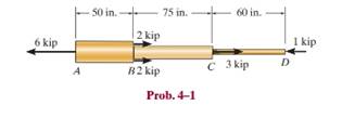
The copper shaft is subjected to the axial loads shown. Determine the displacement of end
Want to see the full answer?
Check out a sample textbook solution
Chapter 4 Solutions
Mechanics of Materials


- The tool shown is made up of an oak wood part. The tool works in torsion and the allowable shear stress for the wood is 213 psi. If the wooden handle has as a minimum section a circular area of diameter 1.4, find the maximum allowable torque T. Express the result in Ib-in with a decimal approximation T D Tarrow_forwardtwo solid steel shafts of different diameters are joined together at point C. the diameter of the smaller shaft is 0.5 in, while the diameter of the larger shaft is 1 in. if the supports at both ends, A & B, are unyielding / rigid, and a counterclockwise torque of 500 ft lb at point D, determine the maximum shear stress in the shaft in ksi. The modulus of rigidity for steel is 10800 ksi.Show full solution pleasearrow_forwardThe electric motor exerts a torque of 800 N- m on the steel shaft ABCD when it is rotating at a constant speed. The angle of twist between A and D is limited to 1.50 degree. Use maximum shear = 60 MPa and modulus of rigidity = 77 GPa. Solve its torque for each shaft AB and BC. And determine the diameter of the Shaft based on strength. 300 N.m 500 N.m 0.4 m 0.6 m 0.3 marrow_forward
- Two solid steel shafts of different diameters are joined together at point C. The diameter of the smaller shaft is 0.5 inch, while the diameter of the larger shaft is 1 inch. If the supports at both ends, A & B, are unyielding / rigid, and a counterclockwise torque of 500 ft lb is applied at point D, determine the maximum shear stress in the shaft in ksi. The modulus of rigidity for steel is 10800 ksi. 8 in 5 in 12 inarrow_forward4. The shaft below is hollow from A to B and solid from B to C. Determine the maximum shear stress in the shaft. The shaft has an outer diameter of &0mm and the thickness of the wall of the hollow segment is 10mm. Please note there are two different formula for solid and hollow shaft. 4 kN-m 2 kN marrow_forwardIf the following solid shaft has a diameter of 20 mm, determine the following: a- a - The polar moment of inertia for the shaft. b- The absolute maximum shear stress developed in the shaft. b- c- The angle of twist of the end B. Take G= 75 GPa.arrow_forward
- 4. The shaft below is hollow from A to B and solid from B to C. Determine the maximum shear stress in the shaft. The shaft has an outer diameter of 80mm and the thickness of the wall of the hollow segment is 10mm. Please note there are two different formula for solid and hollow shaft. 4 kN-m 2 kN-marrow_forwardThe shaft is made from a solid steel section AB and a tubular portion made of steel and having a brass core. If it is fixed to a rigid support at A, and a torque of T = 50 lb.ft is applied to it at C, determine the rotation angle that occurs at C relative to A and compute the maximum shear stress and maximum shear strain in the brass and steel. Take Gst = 11500 ksi, Gbr = 5600 Ksi. 3 ft 0.5 in. B 1 in. T = 50 lb•ftarrow_forwardThe shaft consists of three concentric tubes, each made from the same material and having inner and outer radii as given below. Length of shaft is 2m. One end is fixed to the wall and to the other end a disc is attached. If a torque of T =800 N.m is applied at the disc end, determine the maximum shear stress in the shaft. 1. Inner tube: r; = 20mm, r, = 25 mm 2. Center tube: r; = 26 mm, r. = 30 mm 3. Outer tube: r = 32mm, r, = 38mmarrow_forward
- 3. The rigid bars AB and CD are supported by pins at A and D. The vertical rods are made of aluminum and bronze. Determine the vertical displacement of the point where the force P = 10 kips is applied. Neglect the weights of the members. Aluminum L= 4 f A=0.75 in. E= 10x 10 psi B 4 ft Bronze L= 5 A A=0.25 in.? E= 12x 10 psi 2 ft--2 ft-→arrow_forward1. The composite shaft, consisting of aluminum, copper, and steel sections, is subjected to the loading shown. Determine the displacement of B with respect to C and the normal stress in each section. The cross-sectional area and modulus of elasticity for each section are shown in the figure. Neglect the size of the collars at B and C. Aluminum Eal = 70 GPa AAB = 58 mm² 9 kN A Copper Ecu = 126 GPa ABC = 77 mm² 450 mm 16 kN 斤。 16 kN -300 mm BL Steel Est = 200 GPa ACD = 39 mm² 8 kN 8 kN -400 mm 7 kNarrow_forwardThe 20-mm-diameter A-36 steel rod is subjected to the axial forces shown. Determine the displacement of end C with respect to the fixed support at A.arrow_forward
 Elements Of ElectromagneticsMechanical EngineeringISBN:9780190698614Author:Sadiku, Matthew N. O.Publisher:Oxford University Press
 Mechanics of Materials (10th Edition)Mechanical EngineeringISBN:9780134319650Author:Russell C. HibbelerPublisher:PEARSON
 Thermodynamics: An Engineering ApproachMechanical EngineeringISBN:9781259822674Author:Yunus A. Cengel Dr., Michael A. BolesPublisher:McGraw-Hill Education
 Control Systems EngineeringMechanical EngineeringISBN:9781118170519Author:Norman S. NisePublisher:WILEY
 Mechanics of Materials (MindTap Course List)Mechanical EngineeringISBN:9781337093347Author:Barry J. Goodno, James M. GerePublisher:Cengage Learning
 Engineering Mechanics: StaticsMechanical EngineeringISBN:9781118807330Author:James L. Meriam, L. G. Kraige, J. N. BoltonPublisher:WILEY