
Mechanics of Materials
11th Edition
ISBN: 9780137605460
Author: Russell C. Hibbeler
Publisher: Pearson Education (US)
expand_more
expand_more
format_list_bulleted
Videos
Textbook Question
Chapter 4.2, Problem 4P
The A-36 steel rod is subjected to the loading shown. If the cross-sectional area of the rod is
Expert Solution & Answer
Want to see the full answer?
Check out a sample textbook solution
Students have asked these similar questions
The 20-mm-diameter A-36 steel rod is subjected to the axial forces shown. Determine the displacement of end C with respect to the fixed support at A.
02:27
MENG360 - C...
Problems (8th edition): 4.4 - 4.6 – 4.14 - 4.19
1
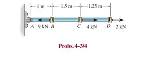
*4-4. The A-36 steel rod is subjected to the loading
shown. If the cross-sectional area of the rod is 50 mm²,
determine the displacement of C. Neglect the size of the
couplings at B, C, and D.
1m
1.5 m
–1.25 m ·
ÞA 9 kN B
C 4 kN
D 2 kN
4-6. The bar has a cross-sectional area of 3 in?, and
E = 35(10) ksi. Determine the displacement of its end A
when it is subjected to the distributed loading.
The spring ABC has a stiffness of 500N/m and an unstretched length of 6m. Calculate the
horizontal force, F applied to the cord which is attached at B so that the displacement of
the pulley from the wall is d= 1.5m.
A
k = 500 N/m
6 m
F
k = 500 N/m
Fig. Q3
Force equation:
Force equation 3D
Moment 3D
Cosine rule
R - 4 +B-2AB cos e
F- Fi+Fj+Fk
Ff = F +F +F
moment about a point
M-rxF
Sine rule
F|
di+dj+dk
F F3
Fc
sin 4 sin B sinC
moment about an axis
M=rF
Force resultant
R-R
R +R
R.
8= tan
R
Chapter 4 Solutions
Mechanics of Materials
Ch. 4.2 - The 20-mm-diameter A-36 steel rod is subjected to...Ch. 4.2 - Segments AB and CD of the assembly are solid...Ch. 4.2 - The 30-mm-diameter A992 steel rod is subjected to...Ch. 4.2 - If the 20-mm-diameter rod is made of A-36 steel...Ch. 4.2 - The 20-mm-diameter 2014-T6 aluminum rod is...Ch. 4.2 - The 20-mm-diameter 2014-T6 aluminum rod is...Ch. 4.2 - The copper shaft is subjected to the axial loads...Ch. 4.2 - The A-36 steel rod is subjected to the loading...Ch. 4.2 - The A-36 steel rod is subjected to the loading...Ch. 4.2 - The A-36 steel drill shaft of an oil well extends...
Ch. 4.2 - Prob. 8PCh. 4.2 - The post is made of Douglas fir and has a diameter...Ch. 4.2 - The post is made of Douglas fir and has a diameter...Ch. 4.2 - The coupling rod is subjected to a force of 5 kip....Ch. 4.2 - The pipe is stuck in the ground so that when it is...Ch. 4.2 - The assembly consists of three titanium...Ch. 4.2 - The assembly consists of two rigid bars that are...Ch. 4.2 - The truss consists of three members, each made...Ch. 4.2 - Solve Prob. 426 when the load P acts vertically...Ch. 4.2 - The ball is truncated at its ends and is used to...Ch. 4.5 - The column is constructed from high-strength...Ch. 4.5 - The column is constructed from high-strength...Ch. 4.5 - The A-36 steel pipe has a 6061-T6 aluminum core....Ch. 4.5 - The 304 stainless steel post A has a diameter of...Ch. 4.5 - The 304 stainless steel post A is surrounded by a...Ch. 4.5 - The 10-mm-diameter steel bolt is surrounded by a...Ch. 4.5 - The rigid beam is supported by the three suspender...Ch. 4.5 - The bolt AB has a diameter of 20 mm and passes...Ch. 4.5 - If the gap between C and the rigid wall at D is...Ch. 4.5 - The support consists of a solid red brass C83400...Ch. 4.5 - Prob. 55PCh. 4.5 - The three A-36 steel wires each have a diameter of...Ch. 4.5 - The A-36 steel wires AB and AD each have a...Ch. 4.5 - The assembly consists of two posts AB and CD each...Ch. 4.5 - The assembly consists of two posts AB and CD each...Ch. 4.5 - The assembly consists of two posts AB and CD each...Ch. 4.5 - The wheel is subjected to a force of 18 kN from...Ch. 4.6 - The C83400-red-brass rod AB and 2014-T6- aluminum...Ch. 4.6 - The assembly has the diameters and material...Ch. 4.6 - Prob. 72PCh. 4.6 - Prob. 77PCh. 4.6 - Prob. 80PCh. 4.6 - The 50-mm-diameter cylinder is made from Am...Ch. 4.6 - The 50-mm-diameter cylinder is made from Am...Ch. 4.6 - The metal strap has a thickness t and width w and...Ch. 4.9 - Determine the maximum normal stress developed in...Ch. 4.9 - If the allowable normal stress for the bar is...Ch. 4.9 - Prob. 89PCh. 4.9 - The A-36 steel plate has a thickness of 12 mm. If...Ch. 4.9 - Determine the maximum axial force P that can be...Ch. 4.9 - Determine the maximum normal stress developed in...Ch. 4.9 - The member is to be made from a steel plate that...Ch. 4.9 - Prob. 96PCh. 4.9 - The bar has a cross-sectional area of 0.5 in2 and...Ch. 4.9 - The distributed loading is applied to the rigid...Ch. 4.9 - The distributed loading is applied to the rigid...Ch. 4.9 - The rigid lever arm is supported by two A-36 steel...Ch. 4.9 - The rigid lever arm is supported by two A-36 steel...Ch. 4.9 - The wire BC has a diameter of 0.125 in. and the...Ch. 4.9 - Prob. 104PCh. 4.9 - Prob. 106PCh. 4 - The assembly consists of two A992 steel bolts AB...Ch. 4 - The assembly shown consists of two A992 steel...Ch. 4 - The rods each have the same 25-mm diameter and...Ch. 4 - Two A992 steel pipes, each having a...Ch. 4 - The force P is applied to the bar, which is made...Ch. 4 - The 2014-T6 aluminum rod has a diameter of 0.5 in....Ch. 4 - The 2014-T6 aluminum rod has a diameter of 0.5 in....Ch. 4 - The rigid link is supported by a pin at A and two...Ch. 4 - The joint is made from three A992 steel plates...
Knowledge Booster


Learn more about
Need a deep-dive on the concept behind this application? Look no further. Learn more about this topic, mechanical-engineering and related others by exploring similar questions and additional content below.Similar questions
- The rigid bar AB and CD are supported by pins at A and D. the vertical rods are made of aluminum and bronze. Determine the vertical displacement of the point where the force P= 10 kips is applied. Neglect the weight of the members.arrow_forwardThe assembly below consists of a steel rod CB and an aluminium rod BA, each having a diameter of 12 mm. If the rod is subjected to the axial loadings at A and at the coupling B, determine the displacement of the coupling B and the end A. The unstretched length of each segment is shown below. Neglect the size of the connections at B and C, and assume that they are rigid. Est = 200 GPa, Eal = 70 GPa.arrow_forwardThe 500-kg large chandelier is suspended from the wall and ceiling using rods AB and BC which have diameters of 8 mm and 10 mm, respectively. Determine the angle 0 so that th normal displacement ô in both rods is the same. Both rods are made of Aluminum materia of E = 70 GPA. Also, determine the force in each rod and the normal displacement.arrow_forward
- *4-4. The A-36 steel rod is subjected to the loading shown. If the cross-sectional area of the rod is 50 mm2, determine the displacement of C. Neglect the size of the couplings at B, C, and D. -1 m - 1.5 m- -1.25 m · A 9 kN B C 4 kN D 2 kNarrow_forwardIf the 20-mm-diameter rod is made of A-36 steel and the stiffness of the spring is k = 50 MN>m, determine the displacement of end A when the 60-kN force is applied.arrow_forwardProblem 2 The series of bars shown have their diameters from left to right decreasing by 3 mm, and lengths increasing correspondingly by 0.3 m. If the leftmost member has a diameter and length of 28 mm, 1.8 m, respectively, determine the nodal displacements, member forces and the value of P if the node where P acts undergoes a rightward displacement of 4.5 mm. E=180 GPa for all members. Use your calculator. 90 N/mm 45 N/mm 60 N/mm 30 KN -50 KNarrow_forward
- The two shafts are made of A-36 steel. Each has a diameter of 25 mm and they are connected using the gears fixed to their ends. Their other ends are attached to fixed supports at A and B. They are also supported by journal bearings at C and D, which allow free rotation of the shafts along their axes. If a torque of 500 N.m is applied to the gear at E as shown, determine the reactions at A and B.arrow_forwardThe bracket is held to the wall using three A-36 steel bolts at B, C, and D. Each bolt has a diameter of 0.5 in. and an unstretched length of 2 in. If a force of 800 lb is placed on the bracket as shown, determine how far, s, the top bracket at bolt D moves away from the wall. For the calculation, assume that the bolts carry no shear; rather, the vertical force of 800 lb is supported by the toe at A. Also, assume that the wall and bracket are rigid. A greatly exaggerated deformation of the bolts is shown.arrow_forwardF4-3. The 30-mm-diameter A-36 steel rod is subjected to the loecing shown. Determine the displacement of end A with respect tc end C. 30 kN 90 kN B 30 kN 400 mm 600 mm -0.772 -0.154 -1.356 -0.098arrow_forward
- The L-shaped frame is made from two fixed-connected segments. Determine the horizontal displacement of the end C. Use the method of virtual work. EI is constant.arrow_forwardAs the electric motor rotates at a constant speed, it applies a torque of 500 Nm to the ABCD shaft. Determine the torsion angle between B and C since G = 27 GPa and the torques shown in the figure are applied to the pulleys B and C.arrow_forwardThe steel bars AC and BC, each of cross-sectional area 120 mm2, are joined at C with a Determine the displacement of point C caused by the 15-kN load. Use E = 200 GPa for steel.arrow_forward
arrow_back_ios
SEE MORE QUESTIONS
arrow_forward_ios
Recommended textbooks for you
 International Edition---engineering Mechanics: St...Mechanical EngineeringISBN:9781305501607Author:Andrew Pytel And Jaan KiusalaasPublisher:CENGAGE L
International Edition---engineering Mechanics: St...
Mechanical Engineering
ISBN:9781305501607
Author:Andrew Pytel And Jaan Kiusalaas
Publisher:CENGAGE L
Mechanical SPRING DESIGN Strategy and Restrictions in Under 15 Minutes!; Author: Less Boring Lectures;https://www.youtube.com/watch?v=dsWQrzfQt3s;License: Standard Youtube License