
Mechanics of Materials
11th Edition
ISBN: 9780137605460
Author: Russell C. Hibbeler
Publisher: Pearson Education (US)
expand_more
expand_more
format_list_bulleted
Concept explainers
Videos
Textbook Question
Chapter 4, Problem 7RP
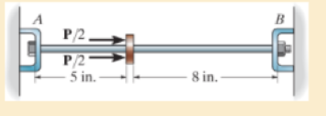
The 2014-T6 aluminum rod has a diameter of 0.5 in. and is lightly attached to the rigid supports at A and B when T1 = 70°F. Determine the force P that must be applied to the collar so that, when T = 0°F, the reaction at B is zero.
R4–7
Expert Solution & Answer
Want to see the full answer?
Check out a sample textbook solution
Students have asked these similar questions
R9-6. The 2014-T6 aluminum rod has a diameter of 12
mm and is lightly attached to the rigid supports at A and B
when T, = 40°C. Determine the force P that must be
applied to the collar so that, when T = 0 "C, the reaction at
B is zera.
P/2.
P/2
-125 mm
- 200 mm-
Bar AD is attached at A and C to pinned collars that can
move freely on the rods but don't restrain rotation. If the
cord BE is at a 30° from vertical, determine the tension
in the cord and the reactions at A and C.
Answers: T=69.3 N, A=140 N, C=180 N
30°
B
a
E
30°
C
-0.2 m-0.2 m 0.2 m-
80 N
OD
1.If d= 1.5 mm, and θ= 30∘, determine the normal reaction at the smooth support A if P = 900 N. Neglect the weight of the bar.
NA=?
2.Determine the normal reaction at the smooth support B
NB=?
3.Determine the required distance a for the placement of the roller.
a=?
Chapter 4 Solutions
Mechanics of Materials
Ch. 4.2 - The 20-mm-diameter A-36 steel rod is subjected to...Ch. 4.2 - Segments AB and CD of the assembly are solid...Ch. 4.2 - The 30-mm-diameter A992 steel rod is subjected to...Ch. 4.2 - If the 20-mm-diameter rod is made of A-36 steel...Ch. 4.2 - The 20-mm-diameter 2014-T6 aluminum rod is...Ch. 4.2 - The 20-mm-diameter 2014-T6 aluminum rod is...Ch. 4.2 - The copper shaft is subjected to the axial loads...Ch. 4.2 - The A-36 steel rod is subjected to the loading...Ch. 4.2 - The A-36 steel rod is subjected to the loading...Ch. 4.2 - The A-36 steel drill shaft of an oil well extends...
Ch. 4.2 - Prob. 8PCh. 4.2 - The post is made of Douglas fir and has a diameter...Ch. 4.2 - The post is made of Douglas fir and has a diameter...Ch. 4.2 - The coupling rod is subjected to a force of 5 kip....Ch. 4.2 - The pipe is stuck in the ground so that when it is...Ch. 4.2 - The assembly consists of three titanium...Ch. 4.2 - The assembly consists of two rigid bars that are...Ch. 4.2 - The truss consists of three members, each made...Ch. 4.2 - Solve Prob. 426 when the load P acts vertically...Ch. 4.2 - The ball is truncated at its ends and is used to...Ch. 4.5 - The column is constructed from high-strength...Ch. 4.5 - The column is constructed from high-strength...Ch. 4.5 - The A-36 steel pipe has a 6061-T6 aluminum core....Ch. 4.5 - The 304 stainless steel post A has a diameter of...Ch. 4.5 - The 304 stainless steel post A is surrounded by a...Ch. 4.5 - The 10-mm-diameter steel bolt is surrounded by a...Ch. 4.5 - The rigid beam is supported by the three suspender...Ch. 4.5 - The bolt AB has a diameter of 20 mm and passes...Ch. 4.5 - If the gap between C and the rigid wall at D is...Ch. 4.5 - The support consists of a solid red brass C83400...Ch. 4.5 - Prob. 55PCh. 4.5 - The three A-36 steel wires each have a diameter of...Ch. 4.5 - The A-36 steel wires AB and AD each have a...Ch. 4.5 - The assembly consists of two posts AB and CD each...Ch. 4.5 - The assembly consists of two posts AB and CD each...Ch. 4.5 - The assembly consists of two posts AB and CD each...Ch. 4.5 - The wheel is subjected to a force of 18 kN from...Ch. 4.6 - The C83400-red-brass rod AB and 2014-T6- aluminum...Ch. 4.6 - The assembly has the diameters and material...Ch. 4.6 - Prob. 72PCh. 4.6 - Prob. 77PCh. 4.6 - Prob. 80PCh. 4.6 - The 50-mm-diameter cylinder is made from Am...Ch. 4.6 - The 50-mm-diameter cylinder is made from Am...Ch. 4.6 - The metal strap has a thickness t and width w and...Ch. 4.9 - Determine the maximum normal stress developed in...Ch. 4.9 - If the allowable normal stress for the bar is...Ch. 4.9 - Prob. 89PCh. 4.9 - The A-36 steel plate has a thickness of 12 mm. If...Ch. 4.9 - Determine the maximum axial force P that can be...Ch. 4.9 - Determine the maximum normal stress developed in...Ch. 4.9 - The member is to be made from a steel plate that...Ch. 4.9 - Prob. 96PCh. 4.9 - The bar has a cross-sectional area of 0.5 in2 and...Ch. 4.9 - The distributed loading is applied to the rigid...Ch. 4.9 - The distributed loading is applied to the rigid...Ch. 4.9 - The rigid lever arm is supported by two A-36 steel...Ch. 4.9 - The rigid lever arm is supported by two A-36 steel...Ch. 4.9 - The wire BC has a diameter of 0.125 in. and the...Ch. 4.9 - Prob. 104PCh. 4.9 - Prob. 106PCh. 4 - The assembly consists of two A992 steel bolts AB...Ch. 4 - The assembly shown consists of two A992 steel...Ch. 4 - The rods each have the same 25-mm diameter and...Ch. 4 - Two A992 steel pipes, each having a...Ch. 4 - The force P is applied to the bar, which is made...Ch. 4 - The 2014-T6 aluminum rod has a diameter of 0.5 in....Ch. 4 - The 2014-T6 aluminum rod has a diameter of 0.5 in....Ch. 4 - The rigid link is supported by a pin at A and two...Ch. 4 - The joint is made from three A992 steel plates...
Knowledge Booster


Learn more about
Need a deep-dive on the concept behind this application? Look no further. Learn more about this topic, mechanical-engineering and related others by exploring similar questions and additional content below.Similar questions
- The post is made from 606l-T6 aluminum and has a diameter of 50 mm. It is fixed supported at A and B, and at its center C there is a coiled spring attached to the rigid collar. If the spring is originally uncompressed, determine the reactions at A and B when the force P = 40 kN is applied to the collar.arrow_forwardDetermine the components of reaction at E. Take that P= 5.1 kN and w = 3.6 kN/m (Figure 1) Figure 1 of 1 1.5 m -1.5 marrow_forward*3–20. A vertical force P= 10 lb is applied to the ends of the 2-ft cord AB and spring AC. If the spring has an unstretched length of 2 ft, determine the angle 0 for equilibrium. Take k = 15 lb/ft. 3–21. Determine the unstretched length of spring AC if a force P = 80 lb causes the angle 0 = 60° for equilibrium. Cord AB is 2 ft long. Take k = 50 lb/ft. 2 ft- 2 ft В ww k Probs. 3–20/21arrow_forward
- 4-17 If rope BC will fail when the tension becomes 50 kN, determine the greatest vertical load F that can be applied to the beam at B.What is the magnitude of the reaction at A for this loading? Neglect the thickness of the beam. 26 kN 1312 в -2marrow_forwardThe bar of negligible weight is supported by two springs,each having a stiffness k = 80 N>m. If the springs are originally unstretched, and the force is vertical as shown,determine the angle theta the bar makes with the horizontal,when the 45-N force is applied to the bar. 1.5 m- 3 m C В 45 Narrow_forward3–31. The springs on the rope assembly are originally stretched 1 ft when 0 = 0°. Determine the vertical force F that must be applied so that 0 = 30°. k = 30 lb/ft k= 30 lb/ftarrow_forward
- 4-71. A 1.8-m-long steam pipe is made of A-36 steel with oy = 280 MPa. It is connected directly to two turbines A and B as shown. The pipe has an outer diameter of 100 mm and a wall thickness of 6 mm. The connection was made at T = 20°C. If the turbines' points of attachment are assumed rigid, determine the force the pipe exerts on the turbines when the steam and thus the pipe reach a temperature of T = 135°C. %3D -1.8 m- F = 489 kN F = 100 kN F = 198 kN F= 356 kN %3Darrow_forwardDetermine the components of reaction at D. Take that P1 = 8 kN and P2 = 15 kN.arrow_forwardThe weight W = 9 kN hangs from the cable which passes over the pulley at F. Neglecting the weights of the bars and the pulley, determine the magnitude of the hinge reaction at A in kN. 1.5 m B D 1.5 m R = 0.4 m A W E 2 m 2 marrow_forward
- Problem 2: The pipe assembly is subjected to the 80-N and 50-N forces. Determine the reactions at the fixed support A. 400 mm B 50 N 300 mm 200 mm 200 mm 250 mm 40° 30 F = 80 Narrow_forwardAssuming that P = 48 000N and that it may be applied at any joint on the line FJ, determine the location of P that would cause (a) maximum tension in member HI; (b) maximum compression in member Cl; and (c) maximum tension in member Cl. Also determine the magnitude of the indicated force in each case. a a D E A a F G H Parrow_forwardDetermine the magnitude of the pin force at A. Assume W = 795 lb, a = 3.6 ft, b = 2.7 ft, r = 9 in. r W C Answer: A = i a B a A D lb barrow_forward
arrow_back_ios
SEE MORE QUESTIONS
arrow_forward_ios
Recommended textbooks for you
 Elements Of ElectromagneticsMechanical EngineeringISBN:9780190698614Author:Sadiku, Matthew N. O.Publisher:Oxford University Press
 Mechanics of Materials (10th Edition)Mechanical EngineeringISBN:9780134319650Author:Russell C. HibbelerPublisher:PEARSON
 Thermodynamics: An Engineering ApproachMechanical EngineeringISBN:9781259822674Author:Yunus A. Cengel Dr., Michael A. BolesPublisher:McGraw-Hill Education
 Control Systems EngineeringMechanical EngineeringISBN:9781118170519Author:Norman S. NisePublisher:WILEY
 Mechanics of Materials (MindTap Course List)Mechanical EngineeringISBN:9781337093347Author:Barry J. Goodno, James M. GerePublisher:Cengage Learning
 Engineering Mechanics: StaticsMechanical EngineeringISBN:9781118807330Author:James L. Meriam, L. G. Kraige, J. N. BoltonPublisher:WILEY
Elements Of Electromagnetics
Mechanical Engineering
ISBN:9780190698614
Author:Sadiku, Matthew N. O.
Publisher:Oxford University Press
Mechanics of Materials (10th Edition)
Mechanical Engineering
ISBN:9780134319650
Author:Russell C. Hibbeler
Publisher:PEARSON
Thermodynamics: An Engineering Approach
Mechanical Engineering
ISBN:9781259822674
Author:Yunus A. Cengel Dr., Michael A. Boles
Publisher:McGraw-Hill Education
Control Systems Engineering
Mechanical Engineering
ISBN:9781118170519
Author:Norman S. Nise
Publisher:WILEY
Mechanics of Materials (MindTap Course List)
Mechanical Engineering
ISBN:9781337093347
Author:Barry J. Goodno, James M. Gere
Publisher:Cengage Learning
Engineering Mechanics: Statics
Mechanical Engineering
ISBN:9781118807330
Author:James L. Meriam, L. G. Kraige, J. N. Bolton
Publisher:WILEY
EVERYTHING on Axial Loading Normal Stress in 10 MINUTES - Mechanics of Materials; Author: Less Boring Lectures;https://www.youtube.com/watch?v=jQ-fNqZWrNg;License: Standard YouTube License, CC-BY