
Concept explainers
Videos
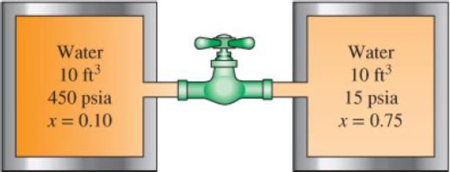
Two 10-ft3 adiabatic tanks are connected by a valve. Initially, one tank contains water at 450 psia with 10 percent quality, while the second contains water at 15 psia with 75 percent quality. The valve is now opened, allowing the water vapor from the high-pressure tank to move to the low-pressure tank until the pressure in the two becomes equal. Determine the final pressure and the final mass in each tank.
FIGURE P4–142E
The final pressure of each tank.
The final mass of each tank.
Answer to Problem 142RP
The final pressure of each tank is
The final mass of each tank is
Explanation of Solution
Write the expression for the energy balance equation.
Here, the total energy entering the system is
Simplify Equation (V) and write energy balance relation of two adiabatic tanks.
Here, the heat to be transfer into the system is
Substitute 0 for
Here, the initial mass of tank A is
Write the expression for initial mass of tank A.
Here, the volume of the tank A is
Write the expression for initial mass of tank B.
Here, the volume of the tank B is
Write the expression for total mass of tank.
Write the expression for initial total internal energy contained in both tanks.
Write the expression for initial is equal to final specific internal energy of tank.
Determine the total volume of both the tanks.
Write the expression for initial is equal to final specific volume of tank.
Write the expression for final mass contained in both tanks.
Conclusion:
At initial pressure and quality of initial state for tank A as 450 psia and 0.10, find the value of initial specific volume and specific internal energy of the tank.
Here, the specific volume of saturated liquid for tank A is
Here, the specific internal energy of saturated liquid for tank A is
Substitute
Substitute
At initial pressure and quality of initial state for tank B as 15 psia and 0.75, find the value of initial specific volume and specific internal energy of the tank.
Here, the specific volume of saturated liquid for tank B is
Here, the specific internal energy of saturated liquid for tank B is
Substitute
Substitute
Substitute
Substitute
Substitute
Substitute
Substitute
Substitute
Substitute
By above calculation from Table A-5E “saturated water” the final pressure of both tanks as
Thus, the final pressure of each tank is
Substitute
Thus, the final mass of each tank is
Want to see more full solutions like this?
Chapter 4 Solutions
Thermodynamics: An Engineering Approach


- 12. Figure Q12 shows a prospective design for a conveyor roller system, for transferring crates, one at a time. The system is made up of two parallel rectangular steel beams, built-in at one end and simply supported at the other, with closely spaced rollers mounted in-between, for the crate to pass over. a) Using Macaulay notation, carry out an analysis of the problem and calculate the deflection of the mid-length point of the beams when the crate is centrally located, midway between A and B. State any important assumptions used in your analysis. [20 marks] b) Comment briefly whether this would be the maximum deflection of the beams when the crate is centrally located. 2 m 8 m A Direction of travel Figure Q12 (side view, only one beam visible) Useful information I for each separate beam = 12 ×10 m² E for both beams = 210 GPa Weight of one crate = 800 N [5 marks] Barrow_forward11. A ring (side view shown in Figure Q11) has a circular solid cross-section of 5 mm diameter. The ring itself has a radius of R = 100 mm and a very narrow gap at point A, that allows the two free ends to be pulled apart by forces P, increasing the size of the gap. ○ P A Figure Q11 P a) Show that the total strain energy of the ring due to the applied forces is: U = 3πP²R³ 2EI [12 marks] b) Find the maximum bending stress produced if forces of P = 8 N are applied. [6 marks] c) What minimum force P would cause the material in the ring to yield and at which locations could this yielding begin to occur? Useful information E for the ring material = 75 GPa Oyield for the ring material = 190 MPa [7 marks]arrow_forwardQ2(15 Marks): From Fig. 2, Determine (a) mass equivalent in term x2, (b) stiffness equivalent in term x2, and (c) the natural frequency for the system in term x2. Note: (1) J Cylinder = mcr? J link (2) 2 3 Pulley, mass moment of inertia J Rigid link 1 (mass m₁), rotates with pulley. about O Cylinder, mass m Adherence to the symbols as in the question 152 153 xx(1) Fig. (2) m k₁ nimmunizmu Rigid link 2 (mass m₂)arrow_forward
- Q3-B (7 Marks): A mass (m) is suspended from a spring of stiffness 4000 N/m and is subjected to a harmonic force having an amplitude of 100 N and a frequency of 5 Hz. The amplitude of the forced motion of the mass is observed to be 20 mm. Find the value of mass (m).arrow_forwardFig. (2) Q3-A (8 Marks): An automobile is modeled as a single-degree-of-freedom system vibrating in the vertical direction. It is driven along a road whose elevation varies sinusoidally. The distance from peak to trough is 0.2 m and the distance along the road between the peaks is 35 m. If the natural frequency of the automobile is 2 Hz and the damping ratio of the shock absorbers is 0.15, determine the amplitude of vibration of the automobile at a speed of 60 km/hour 6.18arrow_forward2. Q4(15 Marks): The motor-pump system shown in Fig. 4. is modeled as a rigid bar of mass m=50 kg and mass moment of inertia Jo=100 kg-m. The foundation of the system can be replaced by two springs of stiffness k=500 N/m and k₂-200 N/m and L=1 m. Determine the natural frequencies of the system. Motor, Fig. (4) 1 6(1) Pump C.G. x(1) x₁(1) Base (a) Foundation (b) C.G. m, Jo x2(1)arrow_forward
- Q5(15 marks): Two equal pendulum free to rotate counterclockwise about the x-x axis are couple together by a rubber hose of torsional stiffness K lb.in/rad.as shown in Fig.5. determine the natural frequencies and mode shape for the normal modes of vibration. If L=19.3 in., W=3.86 lb, and k=20 lb.in/rad. Note: J=mL2 X (1) m 2 mc² 2 Xarrow_forwardUniversity of Babylon College of Engineering\Al-Musayab Automobile Engineering Department Final Examination/1st Attempt جامعة بابل Subject: I. C. Engines I Maximum Time: 3 Hours Class: 3rd Date: / / 2023 Answer 07 of the following questions (First Semester) 2022/2023 (1) Choose the correct answer for eight only from below 1- Indicator diagram shows for one complete revolution of crank Maximum mark: 50 Deg. a) variation of kinetic heat in the cylinder. b) variation of pressure head in the cylinder c) variation of kinetic and pressure heat in the cylinder. d) none of the above. 2- A carburetor is used to supply (a) petrol, air and lubricating oil (b) air and diesel (e) petrol and lubricating oil (d) petrol and air. 3- In a four stroke cycle petrol engine, the charge is compressed when a) inlet valve is closed. b) exit valve is closed. c) both inlet and exit valves are closed. d) both inlet and exit valves are open. (8 deg.) 4- For an engine operating on air standard Otto cycle, the…arrow_forward(6) Determine the sizes of fuel orifice to give a 13.5 air fuel ratio, if the venture throat has 3 cm diameter and the pressure drop in the venture is 6.5 cm Hg. The air temperature and pressure at carburetor entrance are 1 bar and 27 °C respectively. The fuel orifice is at the same level as that of the float chamber. Take density of gasoline as (7 deg.) 740 kg/m³ and discharge coefficient as unity. Assume atmospheric pressure to be 76 cm of Hg. (7) A four-cylinder, four-stroke internal combustion engine has a bore of 87 mm. and a stroke of 77 mm. The clearance volume is 17% of the stroke volume and the engine with speed of 2700 rpm. The processes within each cylinder are modeled as an Otto cycle with a pressure of 1 atm and a temperature of 17 °C at the beginning (7 deg.) of compression. The maximum temperature in the cycle is 2717 °C (a) Draw the P-v diagram; label Pressures, Temperatures, Qin, and Qual (b) Calculate the mass of air at the beginning of the cycle (c) Calculate the…arrow_forward
- University of Babylon College of Engineering\Al-Musayab Automobile Engineering Department Final Examination/1st Attempt جامعة بابل Subject: I. C. Engines I Maximum Time: 3 Hours Class: 3rd Date: / / 2023 Answer 07 of the following questions (First Semester) 2022/2023 (1) Choose the correct answer for eight only from below 1- Indicator diagram shows for one complete revolution of crank Maximum mark: 50 Deg. a) variation of kinetic heat in the cylinder. b) variation of pressure head in the cylinder c) variation of kinetic and pressure heat in the cylinder. d) none of the above. 2- A carburetor is used to supply (a) petrol, air and lubricating oil (b) air and diesel (e) petrol and lubricating oil (d) petrol and air. 3- In a four stroke cycle petrol engine, the charge is compressed when a) inlet valve is closed. b) exit valve is closed. c) both inlet and exit valves are closed. d) both inlet and exit valves are open. (8 deg.) 4- For an engine operating on air standard Otto cycle, the…arrow_forward1,1 51 K/s .. زيد عامر اليوم عند 9:34 م ۱۷۲ من ۱۷۳ University of Babylon College of Engineering Al-Musayab Automobile Engineering Department Final Examination/1" Attempt T19:34 Subject: 1. C. Engines I Maximum Time: 3 Hours Class: 3 Date: 1 / 2023 Answer 07 of the following questions (First Semester) 2022/2023 (1) Choose the correct answer for eight only from below 1- Indicator diagram shows for one complete revolution of crank Maximum mark: 50 Deg. a) variation of kinetic heat in the cylinder. b) variation of pressure head in the cylinder e) variation of kinetic and pressure heat in the cylinder, d) none of the above. 2- A carburetor is used to supply (a) petrol, air and lubricating oil (b) air and diesel (c) petrol and lubricating oil (d) petrol and air. 3- In a four stroke cycle petrol engine, the charge is compressed when a) inlet valve is closed. b) exit valve is closed. e) both inlet and exit valves are closed. d) both inlet and exit valves are open. (8 deg.) 4- For an engine…arrow_forward1- Determine the following: 1- RSHF? 2- C.C.C in tons-ref. 3- Mass of supply air? Fresh Spray chilled water S air 100% RH To 34 C db & 26 wbt S Operation fan room I Exhaust air Ti 22 C db & 50% RHarrow_forward
 Elements Of ElectromagneticsMechanical EngineeringISBN:9780190698614Author:Sadiku, Matthew N. O.Publisher:Oxford University Press
 Mechanics of Materials (10th Edition)Mechanical EngineeringISBN:9780134319650Author:Russell C. HibbelerPublisher:PEARSON
 Thermodynamics: An Engineering ApproachMechanical EngineeringISBN:9781259822674Author:Yunus A. Cengel Dr., Michael A. BolesPublisher:McGraw-Hill Education
 Control Systems EngineeringMechanical EngineeringISBN:9781118170519Author:Norman S. NisePublisher:WILEY
 Mechanics of Materials (MindTap Course List)Mechanical EngineeringISBN:9781337093347Author:Barry J. Goodno, James M. GerePublisher:Cengage Learning
 Engineering Mechanics: StaticsMechanical EngineeringISBN:9781118807330Author:James L. Meriam, L. G. Kraige, J. N. BoltonPublisher:WILEY