
Fundamentals of Electric Circuits
6th Edition
ISBN: 9780078028229
Author: Charles K Alexander, Matthew Sadiku
Publisher: McGraw-Hill Education
expand_more
expand_more
format_list_bulleted
Concept explainers
Videos
Textbook Question
Chapter 4.3, Problem 4PP
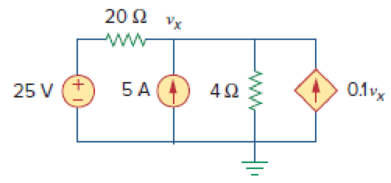
Figure 4.11
Use superposition to find vx in the circuit of Fig. 4.11.
Answer: vx = 31.25 V.
Expert Solution & Answer
Want to see the full answer?
Check out a sample textbook solution
Students have asked these similar questions
Problem 4
Consider the circuit in figure 4.
a) Isolate RL and draw the Thevenin Equivalent circuit
at terminals a-b.
b) From part (a), reconnect and determine the value of
R, which absorbs the maximum power.
c) Find this maximum power if I, is 9A.
4 Vx
a
Vx+
RL
AM-
Q4) By using Nodal analysis, find all voltages and currents.
4 k2
VA
1 k2
4 mA
Vc
14
10 V
2 k2
4 k2
Consider the circuit in figure 4.
a) Isolate RL and draw the Thevenin Equivalent circuit
at terminals a-b.
4Vx
a
b) From part (a), reconnect and determine the value of
R which absorbs the maximum power.
c) Find this maximum power if I, is 9A.
Vx+
2
AM
Chapter 4 Solutions
Fundamentals of Electric Circuits
Ch. 4.2 - Figure 4.3 For Practice Prob. 4.1. For the circuit...Ch. 4.2 - Figure 4.5 For Practice Prob. 4.2. Assume that Vo...Ch. 4.3 - Figure 4.8 Using the superposition theorem, find...Ch. 4.3 - Figure 4.11 Use superposition to find vx in the...Ch. 4.3 - Find I in the circuit of Fig. 4.14 using the...Ch. 4.4 - Find io in the circuit of Fig. 4.19 using source...Ch. 4.4 - Use source transformation to find ix in the...Ch. 4.5 - Using Thevenins theorem, find the equivalent...Ch. 4.5 - Find the Thevenin equivalent circuit of the...Ch. 4.5 - Obtain the Thevenin equivalent of the circuit in...
Ch. 4.6 - Find the Norton equivalent circuit for the circuit...Ch. 4.6 - Find the Norton equivalent circuit of the circuit...Ch. 4.8 - Determine the value of RL that will draw the...Ch. 4.9 - Rework Practice Prob. 4.9 using PSpice. Find the...Ch. 4.9 - Fin d the maximum power transferred to RL if the...Ch. 4.10 - The measured open-circuit voltage across a certain...Ch. 4.10 - Prob. 17PPCh. 4.10 - Obtain the current through the galvanometer,...Ch. 4 - The current through a branch in a linear network...Ch. 4 - For superposition, it is not required that only...Ch. 4 - The superposition principle applies to power...Ch. 4 - Refer to Fig. 4.67. The Thevenin resistance at...Ch. 4 - The Thevenin voltage across terminals a and b of...Ch. 4 - The Norton current at terminals a and b of the...Ch. 4 - The Norton resistance RN is exactly equal to the...Ch. 4 - Which pair of circuits in Fig. 4.68 are...Ch. 4 - A load is connected to a network. At the terminals...Ch. 4 - The source is supplying the maximum power to the...Ch. 4 - Calculate the current io in the circuit of Fig....Ch. 4 - Using Fig. 4.70, design a problem to help other...Ch. 4 - (a) In the circuit of Fig. 4.71, calculate vo and...Ch. 4 - Use linearity to determine io in the circuit of...Ch. 4 - For the circuit in Fig. 4.73, assume vo = 1 V, and...Ch. 4 - For the linear circuit shown in Fig. 4.74, use...Ch. 4 - Use linearity and the assumption that Vo = 1 V to...Ch. 4 - Using superposition, find Vo in the circuit of...Ch. 4 - Given that I = 6 amps when Vs = 160 volts and Is =...Ch. 4 - Using Fig. 4.78, design a problem to help other...Ch. 4 - Use the superposition principle to find io and vo...Ch. 4 - Determine vo in the circuit of Fig. 4.80 using the...Ch. 4 - Use superposition to find vo in the circuit of...Ch. 4 - Apply the superposition principle to find vo in...Ch. 4 - For the circuit in Fig. 4.83, use superposition to...Ch. 4 - Given the circuit in Fig. 4.84, use superposition...Ch. 4 - Use superposition to obtain vx in the circuit of...Ch. 4 - Use superposition to find Vo in the circuit of...Ch. 4 - Use superposition to solve for vx in the circuit...Ch. 4 - Use source transformation to reduce the circuit...Ch. 4 - Using Fig. 4.89, design a problem to help other...Ch. 4 - For the circuit in Fig, 4.90, use source...Ch. 4 - Referring to Fig. 4.91, use source transformation...Ch. 4 - Use source transformation to find the voltage Vx...Ch. 4 - Obtain vo in the circuit of Fig. 4.93 using source...Ch. 4 - Use source transformation to find io in the...Ch. 4 - Apply source transformation to find vx in the...Ch. 4 - Use source transformation to find Io in Fig. 4.96....Ch. 4 - Use source transformation to find vo in the...Ch. 4 - Use source transformation on the circuit shown in...Ch. 4 - Determine vx in the circuit of Fig. 4.99 using...Ch. 4 - Use source transformation to find ix in the...Ch. 4 - Determine the Thevenin equivalent circuit, shown...Ch. 4 - Using Fig. 4.102, design a problem that will help...Ch. 4 - Use Thevenins theorem to find vo in Prob. 4.12....Ch. 4 - Solve for the current i in the circuit of Fig....Ch. 4 - Find the Norton equivalent with respect to...Ch. 4 - Apply Thevenins theorem to find Vo in the circuit...Ch. 4 - Obtain the Thevenin equivalent at terminals a-b of...Ch. 4 - Find the Thevenin equivalent at terminals a-b of...Ch. 4 - Find the Thevenin and Norton equivalents at...Ch. 4 - For the circuit in Fig. 4.109, find the Thevenin...Ch. 4 - Find the Thevenin equivalent looking into...Ch. 4 - For the circuit in Fig. 4.111, obtain the Thevenin...Ch. 4 - Find the Thevenin equivalent of the circuit in...Ch. 4 - Using Fig. 4.113, design a problem to help other...Ch. 4 - Obtain the Thevenin and Norton equivalent circuits...Ch. 4 - Determine the Norton equivalent at terminals a-b...Ch. 4 - Find the Norton equivalent looking into terminals...Ch. 4 - Obtain the Norton equivalent of the circuit in...Ch. 4 - Given the circuit in Fig. 4.117, obtain the Norton...Ch. 4 - For the transistor model in Fig. 4.118, obtain the...Ch. 4 - Find the Norton equivalent at terminals a-b of the...Ch. 4 - Find the Thevenin equivalent between terminals a-b...Ch. 4 - Obtain the Norton equivalent at terminals a-b of...Ch. 4 - Use Nortons theorem to find Vo in the circuit of...Ch. 4 - Obtain the Thevenin and Norton equivalent circuits...Ch. 4 - The network in Fig. 4.124 models a bipolar...Ch. 4 - Determine the Thevenin and Norton equivalents at...Ch. 4 - For the circuit in Fig. 4.126, find the Thevenin...Ch. 4 - Obtain the Thevenin and Norton equivalent circuits...Ch. 4 - Find the Thevenin equivalent of the circuit in...Ch. 4 - Find the Norton equivalent for the circuit in Fig....Ch. 4 - Obtain the Thevenin equivalent seen at terminals...Ch. 4 - For the circuit shown in Fig. 4.131, determine the...Ch. 4 - Find the maximum power that can be delivered to...Ch. 4 - The variable resistor R in Fig. 4.133 is adjusted...Ch. 4 - Consider the 30- resistor in Fig. 4.134. First...Ch. 4 - Find the maximum power transferred to resistor R...Ch. 4 - Determine the maximum power delivered to the...Ch. 4 - For the circuit in Fig. 4.137, what resistor...Ch. 4 - (a) For the circuit in Fig. 4.138, obtain the...Ch. 4 - Determine the maximum power that can be delivered...Ch. 4 - For the bridge circuit shown in Fig. 4.140, find...Ch. 4 - For the circuit in Fig. 4.141, determine the value...Ch. 4 - Solve Prob. 4.34 using PSpice or MultiSim. Let V =...Ch. 4 - Use PSpice or MultiSim to solve Prob. 4.44. For...Ch. 4 - Use PSpice or MultiSim to solve Prob. 4.52.Ch. 4 - Obtain the Thevenin equivalent of the circuit in...Ch. 4 - Use PSpice or MultiSim to find the Thevenin...Ch. 4 - For the circuit in Fig. 4.126, use PSpice or...Ch. 4 - An automobile battery has an open circuit voltage...Ch. 4 - The following results were obtained from...Ch. 4 - When connected to a 4- resistor, a battery has a...Ch. 4 - The Thevenin equivalent at terminals a-b of the...Ch. 4 - A black box with a circuit in it is connected to a...Ch. 4 - A transducer is modeled with a current source Is...Ch. 4 - Consider the circuit in Fig. 4.144. An ammeter...Ch. 4 - Consider the circuit in Fig. 4.145. (a) Replace...Ch. 4 - The Wheatstone bridge circuit shown in Fig. 4.146...Ch. 4 - (a) In the Wheatstone bridge circuit of Fig. 4.147...Ch. 4 - Consider the bridge circuit of Fig. 4.148. Is the...Ch. 4 - The circuit in Fig. 4.149 models a common-emitter...Ch. 4 - An attenuator is an interface circuit that reduces...Ch. 4 - A dc voltmeter with a sensitivity of 10 k/V is...Ch. 4 - A resistance array is connected to a load resistor...Ch. 4 - A common-emitter amplifier circuit is shown in...Ch. 4 - For Practice Prob. 4.18, determine the current...
Knowledge Booster


Learn more about
Need a deep-dive on the concept behind this application? Look no further. Learn more about this topic, electrical-engineering and related others by exploring similar questions and additional content below.Similar questions
- 4.8.1 In the circuit shown in the image below, if V1 = 4.7 V and R1 = 5.2 Q, according to the superposition method, determine voltage vo (in V) if the 9-V power source is turned off. R1 Vo 1Ω 3Ω 5Ω 9 V Please pay attention: the numbers may change since they are randomized. Your answer should keep 3 places after the decimal point. Your Answer: Answerarrow_forward4.1 Find a Thévenin equivalent for the circuit shown with respect the 6 resistor. Use the Thévenin equivalent to find the current in the 6 2 resistor. If the 6 2 resistor were replaced with an 8 V source with positive terminal at the right, what would be the current in the source? 5 ohm w 40V 5 ohm 3 ohm 6 ohm ww 4 ohm 8 ohmarrow_forwardasaparrow_forward
- Q4(a) Find the branch currents /,, through Is in the circuit shown in Figure Q4 (a), by using Kirchhoff's current law (KCL). Also determine the number of nodes in the circuit shown in Figure Q4 (a). 50 A 12 15 10A 100 A 20A 20 A Figure Q4 (a)arrow_forwardProblem 4.89 - Enhanced - with Hints and Feedback The variable resistor R, in the circuit in (Figure 1) is adjusted for maximum power transfer to R₁. Suppose that v₁ = 300 V, and v₂ = 180 V. Figure 102 www 14i is 2002 4 Ω ww 202 www R₂ 302 www 1 of 1 Part B Find the maximum power that can be delivered to Ro Express your answer to three significant figures and include the appropriate units. ► View Available Hint(s) Pmax= 5900 W Submit Previous Answers ✓ Correct Here we learn how to find the maximum power delivered to Ro Part C What percentage of the total power developed in the circuit is delivered to R, found in part A? Express your answer as a percentage to three significant figures. ► View Available Hint(s) 197| ΑΣΦ | 241 % delivered = 50 vec Submit Previous Answers Request Answer X Incorrect; Try Again; 3 attempts remaining %arrow_forwardc) Analyse the steady-state voltage vo(t) of the circuit in Figure Q4(b) if the input voltage is given by: v;(t) = 7.5 cos(2t - 122°) +2.2 cos(6t – 102°) +1.3 cos(10t – 97°) + 0.91 cos(14t – 95°) + ... V Show your answer for the first four terms of the output voltage, Vo(t).arrow_forward
- Q4) Determine the maximum power delivered to the variable resistor R. 3V, 592 ww 1592 592 ww 692 ww Vx www Answers to input: What is the Thevenin equivalent voltage for the circuit from the perspective of R (ie for the circuit excluding R)? What is the Thevenin equivalent resistance for the circuit from the perspective of R (ie for the circuit excluding R)? What is the maximum power that can be delivered to R in mW?arrow_forward(c) For the network of Figure Q4 (c), R = 700 , L=7 H, C= 1/7 F, Calculate the characteristic roots of the circuit. R L ell V C Figure Q4 (c)arrow_forwardFor the shown values and polarities provided, using SUPERPOSITION: a. Find the contribution to Vx from the voltage source only b. Find the contribution to V3 from the current source only 5000 5002 + 9V Vx 1 6mA 1kQ 5002arrow_forward
- 4.70 An automobile battery, when connected to a car radio, provides 12.5 V to the radio. When connected to a set of headlights, it provides 11.7 V to the head- lights. Assume the radio can be modeled as a 6.25 N resistor and the headlights can be modeled as a 0.65 N resistor. What are the Thévenin and Norton equivalents for the battery?arrow_forward4.36 Node Voltage Method. In the circuit of Fig. 4-48 write three node equations for nodes A, B, and C, with node D as the reference, and find the node voltages. Node A: SVA - 2V- 3Vc = 30 Node B: -V +6,- 3Vc =0 from which V = 17, Vg = 9, Vc = 12.33 all in V Ans. Node C: -V-2V+3Vc = 2 20 IA 2A D. Fig. 4-48 wwarrow_forwardD LMH_chapter2-part2-homework. X + O File | C:/Users/DELL/Downloads/LMH_chapter2-part2-homework.pdf D Page view A Read aloud V Draw E Highlight O Erase 3 of 15 HW2 Use superposition to solve for v in the circuit of Fig. 4.87. 2Ω 6 A 4 A 8Ω 4ix 11:00 PM O Type here to search A a O 4) E ENG 3/22/2021arrow_forward
arrow_back_ios
SEE MORE QUESTIONS
arrow_forward_ios
Recommended textbooks for you
 Introductory Circuit Analysis (13th Edition)Electrical EngineeringISBN:9780133923605Author:Robert L. BoylestadPublisher:PEARSON
 Delmar's Standard Textbook Of ElectricityElectrical EngineeringISBN:9781337900348Author:Stephen L. HermanPublisher:Cengage Learning
 Programmable Logic ControllersElectrical EngineeringISBN:9780073373843Author:Frank D. PetruzellaPublisher:McGraw-Hill Education
 Fundamentals of Electric CircuitsElectrical EngineeringISBN:9780078028229Author:Charles K Alexander, Matthew SadikuPublisher:McGraw-Hill Education
 Electric Circuits. (11th Edition)Electrical EngineeringISBN:9780134746968Author:James W. Nilsson, Susan RiedelPublisher:PEARSON
 Engineering ElectromagneticsElectrical EngineeringISBN:9780078028151Author:Hayt, William H. (william Hart), Jr, BUCK, John A.Publisher:Mcgraw-hill Education,
Introductory Circuit Analysis (13th Edition)
Electrical Engineering
ISBN:9780133923605
Author:Robert L. Boylestad
Publisher:PEARSON
Delmar's Standard Textbook Of Electricity
Electrical Engineering
ISBN:9781337900348
Author:Stephen L. Herman
Publisher:Cengage Learning
Programmable Logic Controllers
Electrical Engineering
ISBN:9780073373843
Author:Frank D. Petruzella
Publisher:McGraw-Hill Education
Fundamentals of Electric Circuits
Electrical Engineering
ISBN:9780078028229
Author:Charles K Alexander, Matthew Sadiku
Publisher:McGraw-Hill Education
Electric Circuits. (11th Edition)
Electrical Engineering
ISBN:9780134746968
Author:James W. Nilsson, Susan Riedel
Publisher:PEARSON
Engineering Electromagnetics
Electrical Engineering
ISBN:9780078028151
Author:Hayt, William H. (william Hart), Jr, BUCK, John A.
Publisher:Mcgraw-hill Education,
Nodal Analysis for Circuits Explained; Author: Engineer4Free;https://www.youtube.com/watch?v=f-sbANgw4fo;License: Standard Youtube License