
Concept explainers
Videos
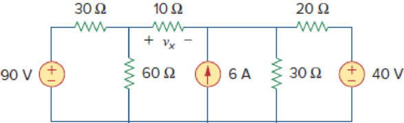
Use superposition to obtain vx in the circuit of Fig. 4.85. Check your result using PSpice or MultiSim.
Figure 4.85
Find the value of the voltage
Answer to Problem 17P
The value of the voltage
Explanation of Solution
Given data:
Refer to Figure 4.85 in the textbook.
Calculation:
In the given circuit, since there are three sources, let
Where
When
The given circuit is modified as shown in Figure 1.
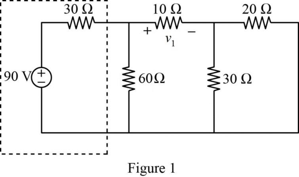
In Figure 1, the voltage source with series resistance is converted into current source with parallel resistance by source transformation method.
That is,
The source transformation is shown in Figure 2.
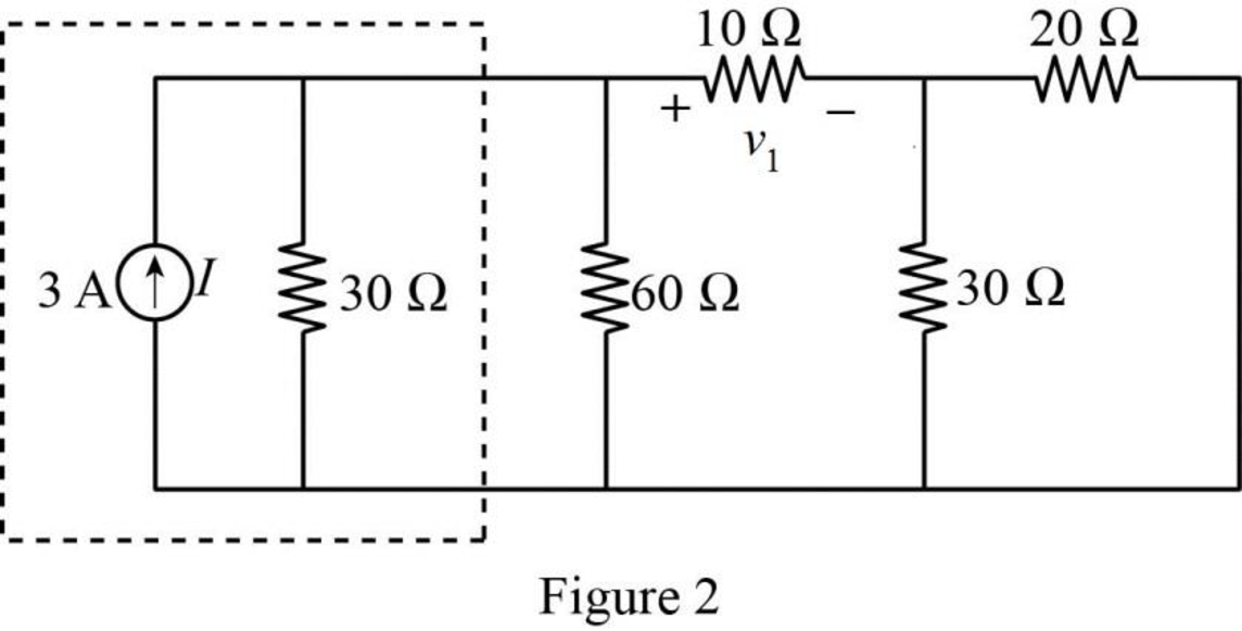
In Figure 2,
Similarly,
The modified Figure is shown in Figure 3.
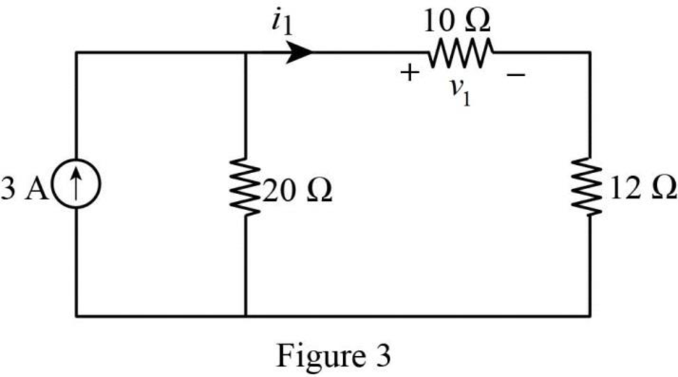
In Figure 3, the current
The voltage
Substitute
When
The given circuit is modified as shown in Figure 4.
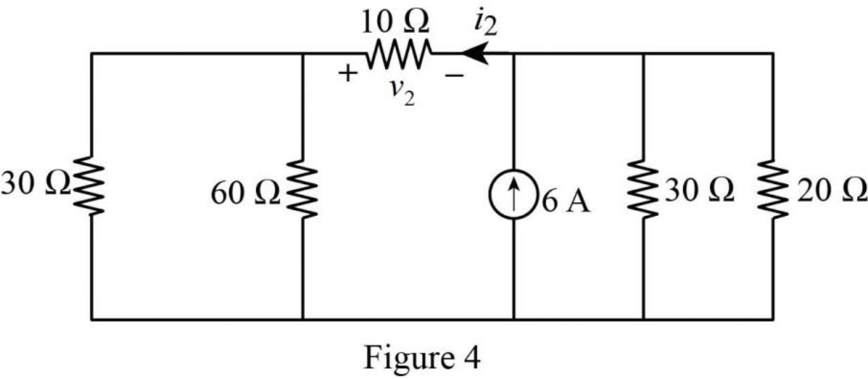
In Figure 4,
Similarly,
The modified Figure is shown in Figure 5.
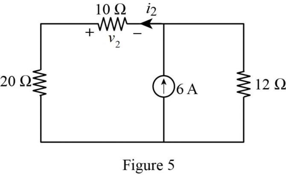
In Figure 5, the current
The voltage
Substitute
When
The given circuit is modified as shown in Figure 6.
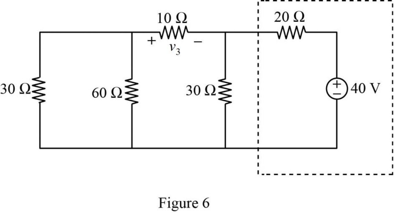
In Figure 6, the voltage source with series resistance is converted into current source with parallel resistance by source transformation method.
That is,
The source transformation is shown in Figure 7.
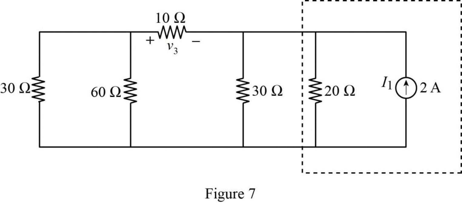
In Figure 7,
Similarly,
The modified Figure is shown in Figure 8.
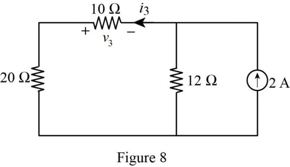
In Figure 8, the current
The voltage
Substitute
The total voltage
Substitute
PSPICE Simulation:
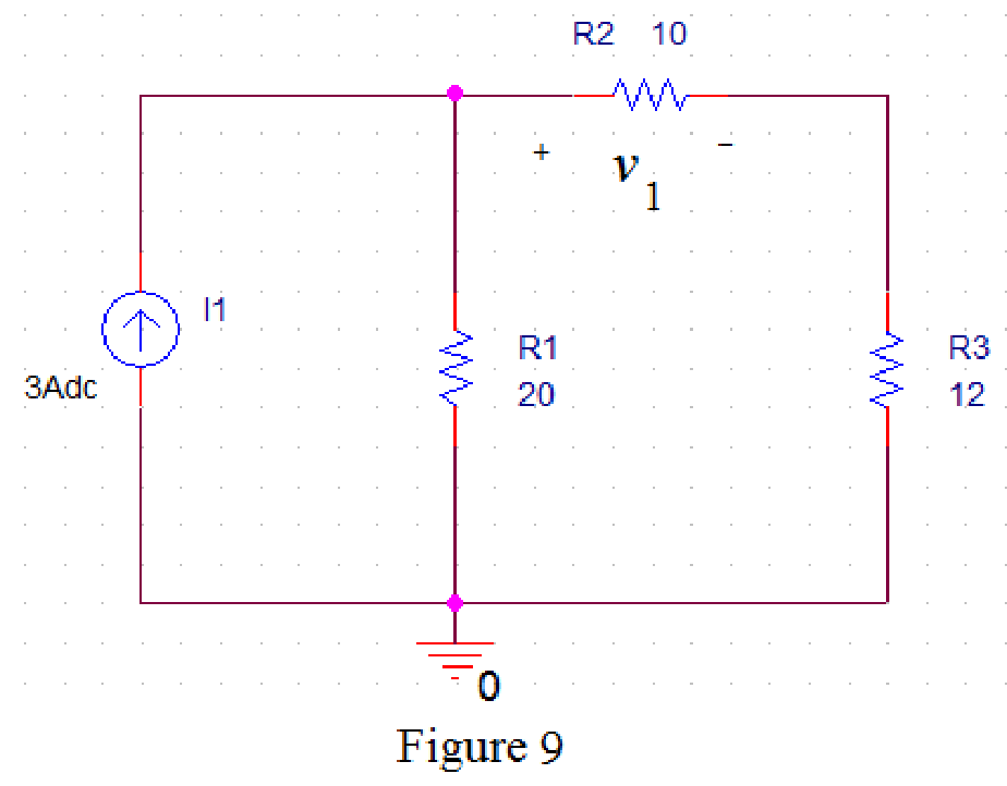
Refer to Figure 3, when
Draw the circuit diagram in PSPICE as shown in Figure 9.
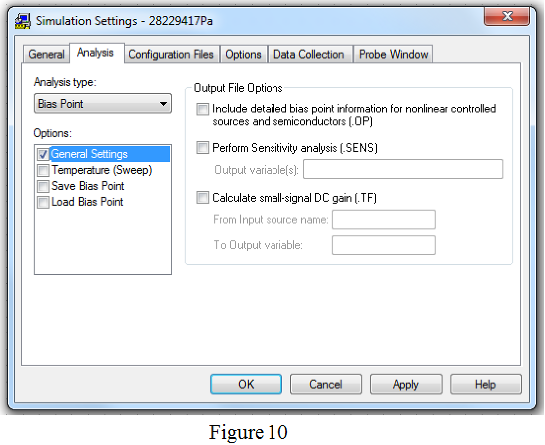
Save the circuit and provide the Simulation Settings as shown in Figure 10.
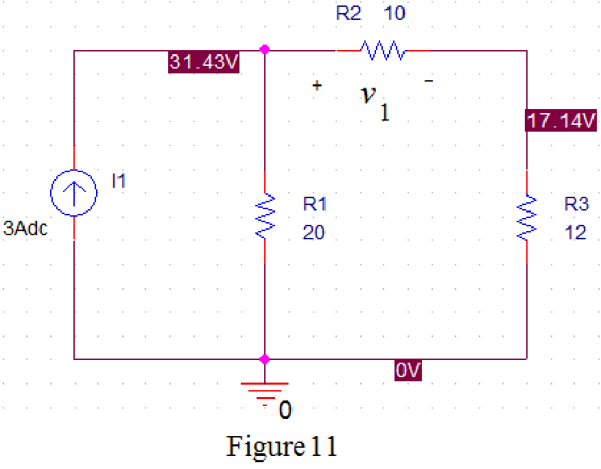
Now run the simulation and the results will be displayed as shown in Figure 11 by enabling “Enable Bias Voltage Display” icon.
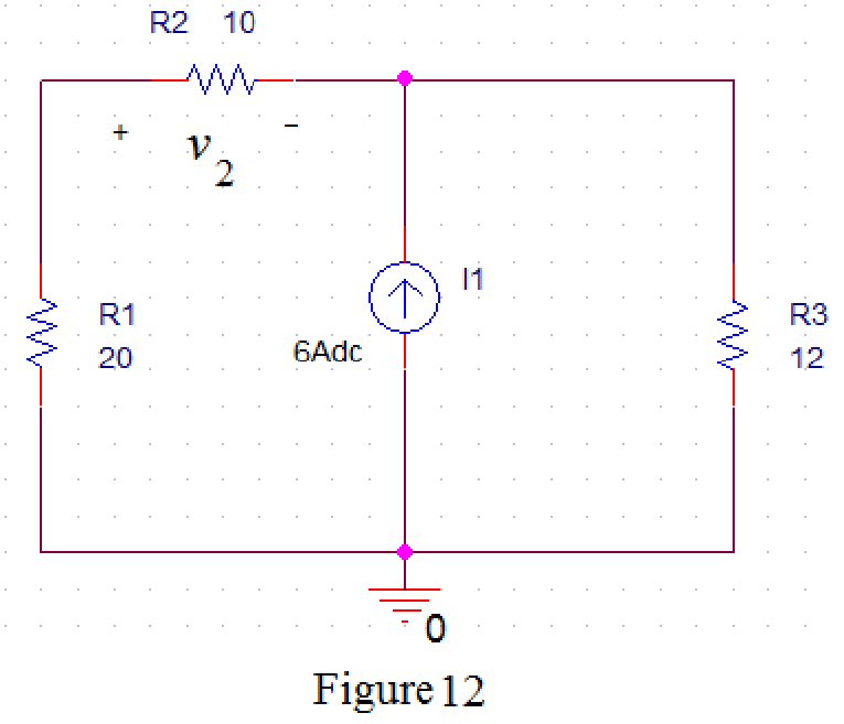
Refer to Figure 5, when
Draw the circuit diagram in PSPICE as shown in Figure 12.
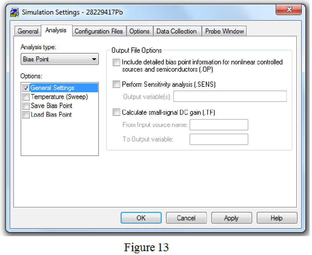
Save the circuit and provide the Simulation Settings as shown in Figure 13.
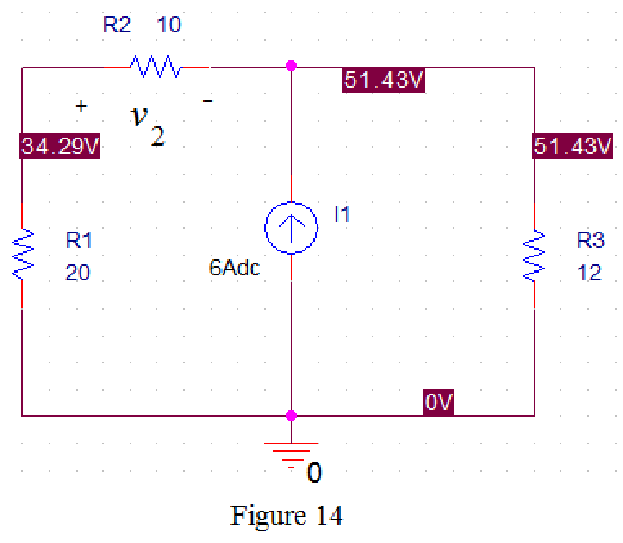
Now run the simulation and the results will be displayed as shown in Figure 14 by enabling “Enable Bias Voltage Display” icon.
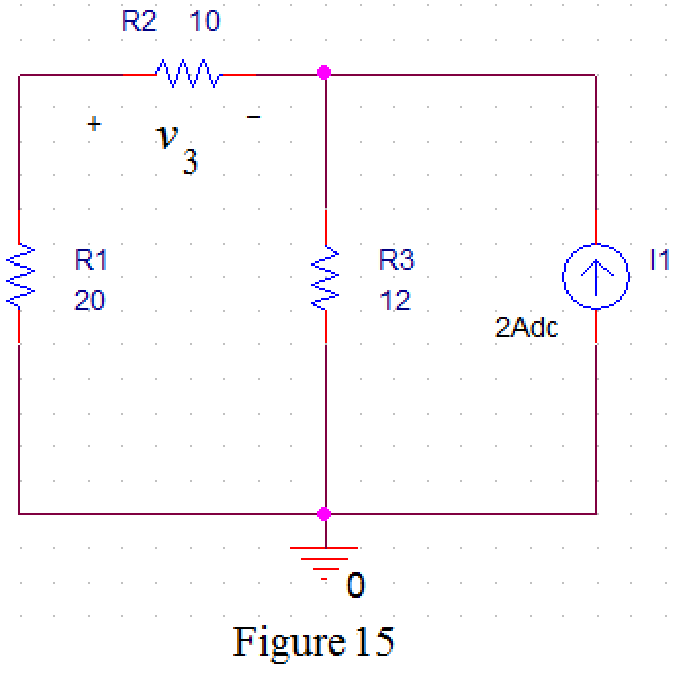
Refer to Figure 8, when
Draw the circuit diagram in PSPICE as shown in Figure 15.
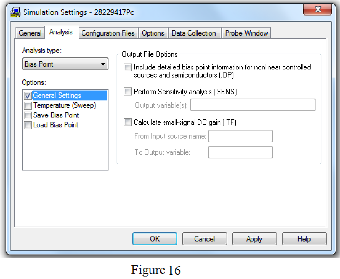
Save the circuit and provide the Simulation Settings as shown in Figure 16.
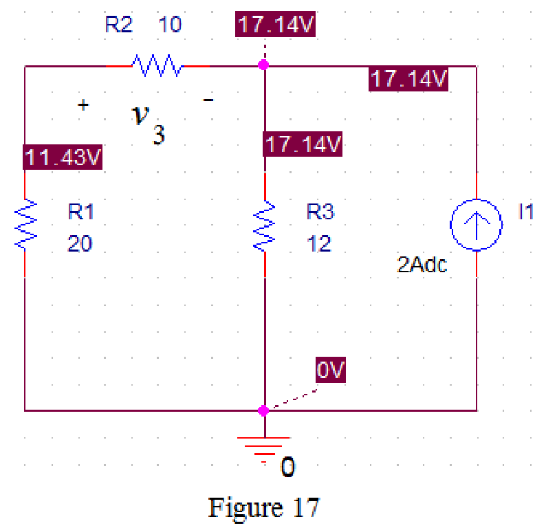
Now run the simulation and the results will be displayed as shown in Figure 17 by enabling “Enable Bias Voltage Display” icon.
From Figure 11, the voltage
From Figure 14, the voltage
From Figure 17, the voltage
Substitute
Conclusion:
Thus, the value of the voltage
Want to see more full solutions like this?
Chapter 4 Solutions
Fundamentals of Electric Circuits
Additional Engineering Textbook Solutions
Electric machinery fundamentals
Fundamentals of Applied Electromagnetics (7th Edition)
ANALYSIS+DESIGN OF LINEAR CIRCUITS(LL)
Loose Leaf for Engineering Circuit Analysis Format: Loose-leaf
Electronics Fundamentals: Circuits, Devices & Applications
Principles and Applications of Electrical Engineering


- Find the Norton equivalent for the circuit in Fig. 4.129arrow_forwardFind the Thevenin equivalent circuit of the circuit in Fig. 4.34 to the left of the terminals.arrow_forwardUsing the superstition theorem, how would I prove the second images problem, given that #2 (voltage source was replaced with a short) measured 5 amps, and #4 (had the current source replaced with an open circuit) measured 1.6 amps?arrow_forward
- 2. Calculate the value of the U2 voltmeter in the circuit given below. Verify your analysis by installing the circuit in the computer program.Opamp supply voltages: V + = 15V, V- = - 15V. I sent you question's image. Can you please verify your results? I only need solution not a computer program.arrow_forward"SUPERPOSITION THEOREM" Please Find the Vo Using SUPERPOSITION THEOREM thankyou very much! I've included a cicruit app to check if your answer was correct and close to the value of currents and voltages which is 0.5V thankyou! I've been testing simple circuits to practice problems using different theorems,I appreciate you very much Thankyou!arrow_forwardCalculate the Thevenin equivalent circuit seen through the terminals (a, b) & draw the equivalent mThevenin equivalent.arrow_forward
- 11 Kelvin Double Bridge is used for the measurement of larger value resistance. Select one: True Falsearrow_forwardUse the superposition theorem to calculate the current in the circuit HELP ME ! PLEASEarrow_forwardFind the Norton equivalent circuit for the circuit in Fig. 4.42, at terminals a-b.arrow_forward
- A black box with a circuit in it is connected to a variable resistor. An ideal ammeter (with zero resistance) and an ideal voltmeter (with infinite resistance) are used to measure current and voltage as shown in Fig. 4.143.arrow_forwardAnalyze the simplified circuit to calculate all the mesh currents and node voltages. Label your results neatly on a circuit diagram. please use mesh analyises thank you..arrow_forwardThe Superposition Principle allows to find specific information in certain branches of an electrical circuit. In the case of the following circuit, by means of this principle, determine what the voltage will be at the resistor R1 terminals answer: VR1 = 508,8 Varrow_forward
 Introductory Circuit Analysis (13th Edition)Electrical EngineeringISBN:9780133923605Author:Robert L. BoylestadPublisher:PEARSON
 Delmar's Standard Textbook Of ElectricityElectrical EngineeringISBN:9781337900348Author:Stephen L. HermanPublisher:Cengage Learning
 Programmable Logic ControllersElectrical EngineeringISBN:9780073373843Author:Frank D. PetruzellaPublisher:McGraw-Hill Education
 Fundamentals of Electric CircuitsElectrical EngineeringISBN:9780078028229Author:Charles K Alexander, Matthew SadikuPublisher:McGraw-Hill Education
 Electric Circuits. (11th Edition)Electrical EngineeringISBN:9780134746968Author:James W. Nilsson, Susan RiedelPublisher:PEARSON
 Engineering ElectromagneticsElectrical EngineeringISBN:9780078028151Author:Hayt, William H. (william Hart), Jr, BUCK, John A.Publisher:Mcgraw-hill Education,