
Fundamentals of Electric Circuits
6th Edition
ISBN: 9780078028229
Author: Charles K Alexander, Matthew Sadiku
Publisher: McGraw-Hill Education
expand_more
expand_more
format_list_bulleted
Concept explainers
Videos
Textbook Question
Chapter 4, Problem 9P
Given that I = 6 amps when Vs = 160 volts and Is = −10 amps and I = 5 amp when Vs = 200 volts and Is = 0, use superposition and linearity to determine the value of I when Vs = 120 volts and Is = 5 amps.
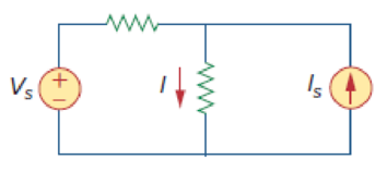
Figure 4.77
Expert Solution & Answer

Trending nowThis is a popular solution!

Students have asked these similar questions
Q/For the circuit in Figure
(1) Determine (Vout).
(2) Calculate the value of (R) that should be used.
(3) Determine the minimum and maximum value of (RL) that can be used.
(4) Determine the minimum and maximum input voltage.
Given
VZ = 15 V, IZ = 17 mA, IZK = 0.25 mA, and ZZ = 140.
+6
VIN
24 V
H
R
www
VOUT
IN4744A
RL
1. The 10M resistor (all resistor values are in Ohms and M = million) represents a scope
input resistance. Calculate the voltage across the 2M resistor and compare (% error) to
the ideal case. An ideal scope input resistance is the same as an ideal internal
resistance of a voltmeter.
15V dc
100k
2M
10M
Replace the 2M resistor with a 100K resistor and calculate the voltage across the 100K
resistor and compare (% error) to the ideal case.
For which resistor value (2M or 100K) does the scope have the greatest “loading”
effect? Justify your answer.
1. When we build our level meter, we will need some fixed voltages to serve as
references for comparison. We can produce these voltage references
through the use of voltage division -- dividing down the positive voltage rail
used to power the op-amps. See Figure 4. Use your results from prelab to
choose values for R1, R2, and R3 such that V₁ = 8 V and V₂ = 4 V.
15V
R
R2
R3
www
V2
ww
Figure 4. Voltage references for the level meter.
Chapter 4 Solutions
Fundamentals of Electric Circuits
Ch. 4.2 - Figure 4.3 For Practice Prob. 4.1. For the circuit...Ch. 4.2 - Figure 4.5 For Practice Prob. 4.2. Assume that Vo...Ch. 4.3 - Figure 4.8 Using the superposition theorem, find...Ch. 4.3 - Figure 4.11 Use superposition to find vx in the...Ch. 4.3 - Find I in the circuit of Fig. 4.14 using the...Ch. 4.4 - Find io in the circuit of Fig. 4.19 using source...Ch. 4.4 - Use source transformation to find ix in the...Ch. 4.5 - Using Thevenins theorem, find the equivalent...Ch. 4.5 - Find the Thevenin equivalent circuit of the...Ch. 4.5 - Obtain the Thevenin equivalent of the circuit in...
Ch. 4.6 - Find the Norton equivalent circuit for the circuit...Ch. 4.6 - Find the Norton equivalent circuit of the circuit...Ch. 4.8 - Determine the value of RL that will draw the...Ch. 4.9 - Rework Practice Prob. 4.9 using PSpice. Find the...Ch. 4.9 - Fin d the maximum power transferred to RL if the...Ch. 4.10 - The measured open-circuit voltage across a certain...Ch. 4.10 - Prob. 17PPCh. 4.10 - Obtain the current through the galvanometer,...Ch. 4 - The current through a branch in a linear network...Ch. 4 - For superposition, it is not required that only...Ch. 4 - The superposition principle applies to power...Ch. 4 - Refer to Fig. 4.67. The Thevenin resistance at...Ch. 4 - The Thevenin voltage across terminals a and b of...Ch. 4 - The Norton current at terminals a and b of the...Ch. 4 - The Norton resistance RN is exactly equal to the...Ch. 4 - Which pair of circuits in Fig. 4.68 are...Ch. 4 - A load is connected to a network. At the terminals...Ch. 4 - The source is supplying the maximum power to the...Ch. 4 - Calculate the current io in the circuit of Fig....Ch. 4 - Using Fig. 4.70, design a problem to help other...Ch. 4 - (a) In the circuit of Fig. 4.71, calculate vo and...Ch. 4 - Use linearity to determine io in the circuit of...Ch. 4 - For the circuit in Fig. 4.73, assume vo = 1 V, and...Ch. 4 - For the linear circuit shown in Fig. 4.74, use...Ch. 4 - Use linearity and the assumption that Vo = 1 V to...Ch. 4 - Using superposition, find Vo in the circuit of...Ch. 4 - Given that I = 6 amps when Vs = 160 volts and Is =...Ch. 4 - Using Fig. 4.78, design a problem to help other...Ch. 4 - Use the superposition principle to find io and vo...Ch. 4 - Determine vo in the circuit of Fig. 4.80 using the...Ch. 4 - Use superposition to find vo in the circuit of...Ch. 4 - Apply the superposition principle to find vo in...Ch. 4 - For the circuit in Fig. 4.83, use superposition to...Ch. 4 - Given the circuit in Fig. 4.84, use superposition...Ch. 4 - Use superposition to obtain vx in the circuit of...Ch. 4 - Use superposition to find Vo in the circuit of...Ch. 4 - Use superposition to solve for vx in the circuit...Ch. 4 - Use source transformation to reduce the circuit...Ch. 4 - Using Fig. 4.89, design a problem to help other...Ch. 4 - For the circuit in Fig, 4.90, use source...Ch. 4 - Referring to Fig. 4.91, use source transformation...Ch. 4 - Use source transformation to find the voltage Vx...Ch. 4 - Obtain vo in the circuit of Fig. 4.93 using source...Ch. 4 - Use source transformation to find io in the...Ch. 4 - Apply source transformation to find vx in the...Ch. 4 - Use source transformation to find Io in Fig. 4.96....Ch. 4 - Use source transformation to find vo in the...Ch. 4 - Use source transformation on the circuit shown in...Ch. 4 - Determine vx in the circuit of Fig. 4.99 using...Ch. 4 - Use source transformation to find ix in the...Ch. 4 - Determine the Thevenin equivalent circuit, shown...Ch. 4 - Using Fig. 4.102, design a problem that will help...Ch. 4 - Use Thevenins theorem to find vo in Prob. 4.12....Ch. 4 - Solve for the current i in the circuit of Fig....Ch. 4 - Find the Norton equivalent with respect to...Ch. 4 - Apply Thevenins theorem to find Vo in the circuit...Ch. 4 - Obtain the Thevenin equivalent at terminals a-b of...Ch. 4 - Find the Thevenin equivalent at terminals a-b of...Ch. 4 - Find the Thevenin and Norton equivalents at...Ch. 4 - For the circuit in Fig. 4.109, find the Thevenin...Ch. 4 - Find the Thevenin equivalent looking into...Ch. 4 - For the circuit in Fig. 4.111, obtain the Thevenin...Ch. 4 - Find the Thevenin equivalent of the circuit in...Ch. 4 - Using Fig. 4.113, design a problem to help other...Ch. 4 - Obtain the Thevenin and Norton equivalent circuits...Ch. 4 - Determine the Norton equivalent at terminals a-b...Ch. 4 - Find the Norton equivalent looking into terminals...Ch. 4 - Obtain the Norton equivalent of the circuit in...Ch. 4 - Given the circuit in Fig. 4.117, obtain the Norton...Ch. 4 - For the transistor model in Fig. 4.118, obtain the...Ch. 4 - Find the Norton equivalent at terminals a-b of the...Ch. 4 - Find the Thevenin equivalent between terminals a-b...Ch. 4 - Obtain the Norton equivalent at terminals a-b of...Ch. 4 - Use Nortons theorem to find Vo in the circuit of...Ch. 4 - Obtain the Thevenin and Norton equivalent circuits...Ch. 4 - The network in Fig. 4.124 models a bipolar...Ch. 4 - Determine the Thevenin and Norton equivalents at...Ch. 4 - For the circuit in Fig. 4.126, find the Thevenin...Ch. 4 - Obtain the Thevenin and Norton equivalent circuits...Ch. 4 - Find the Thevenin equivalent of the circuit in...Ch. 4 - Find the Norton equivalent for the circuit in Fig....Ch. 4 - Obtain the Thevenin equivalent seen at terminals...Ch. 4 - For the circuit shown in Fig. 4.131, determine the...Ch. 4 - Find the maximum power that can be delivered to...Ch. 4 - The variable resistor R in Fig. 4.133 is adjusted...Ch. 4 - Consider the 30- resistor in Fig. 4.134. First...Ch. 4 - Find the maximum power transferred to resistor R...Ch. 4 - Determine the maximum power delivered to the...Ch. 4 - For the circuit in Fig. 4.137, what resistor...Ch. 4 - (a) For the circuit in Fig. 4.138, obtain the...Ch. 4 - Determine the maximum power that can be delivered...Ch. 4 - For the bridge circuit shown in Fig. 4.140, find...Ch. 4 - For the circuit in Fig. 4.141, determine the value...Ch. 4 - Solve Prob. 4.34 using PSpice or MultiSim. Let V =...Ch. 4 - Use PSpice or MultiSim to solve Prob. 4.44. For...Ch. 4 - Use PSpice or MultiSim to solve Prob. 4.52.Ch. 4 - Obtain the Thevenin equivalent of the circuit in...Ch. 4 - Use PSpice or MultiSim to find the Thevenin...Ch. 4 - For the circuit in Fig. 4.126, use PSpice or...Ch. 4 - An automobile battery has an open circuit voltage...Ch. 4 - The following results were obtained from...Ch. 4 - When connected to a 4- resistor, a battery has a...Ch. 4 - The Thevenin equivalent at terminals a-b of the...Ch. 4 - A black box with a circuit in it is connected to a...Ch. 4 - A transducer is modeled with a current source Is...Ch. 4 - Consider the circuit in Fig. 4.144. An ammeter...Ch. 4 - Consider the circuit in Fig. 4.145. (a) Replace...Ch. 4 - The Wheatstone bridge circuit shown in Fig. 4.146...Ch. 4 - (a) In the Wheatstone bridge circuit of Fig. 4.147...Ch. 4 - Consider the bridge circuit of Fig. 4.148. Is the...Ch. 4 - The circuit in Fig. 4.149 models a common-emitter...Ch. 4 - An attenuator is an interface circuit that reduces...Ch. 4 - A dc voltmeter with a sensitivity of 10 k/V is...Ch. 4 - A resistance array is connected to a load resistor...Ch. 4 - A common-emitter amplifier circuit is shown in...Ch. 4 - For Practice Prob. 4.18, determine the current...
Knowledge Booster


Learn more about
Need a deep-dive on the concept behind this application? Look no further. Learn more about this topic, electrical-engineering and related others by exploring similar questions and additional content below.Similar questions
- For the op-amp in Figure 4, find the value of V2. 330 N 2.1 V 100 N 75 k2 V2 2 kN 1 mA 5 kN Figure 4arrow_forwardWhen OP-AMPs are considered ideal in the circuit: a) What is V voltage? b) What is the equivalent resistance of the region inside the rectangle?arrow_forwardQ: For the circuit shown below, calculate the currentrsng through each resistor for the following different input supply volta (9V, 11V,13V), then measure these currents using Multisim applicati for the same input supply voltages (9V, 11V,13V). R = 100 0 IT Vs R4 =400 O R3 = 300 Q R2 = 200 0arrow_forward
- 4. Figure 4 shows a direct-coupled (that is. with no coupling capacitors between stages) two stage amplifier. The DC bias of the first stage sets the de bias of the second. Determine all DC voltages for both stages and the overall AC voltage gain. oVcc=+12 V R1 100 k2 R3 22 k2 R5 10 k2 oVout ViO Q2 R2 22 kN R4 4.7 kN R6 10 k2 Figure 4 10 uF 10 µF Bac = Bpc = 125arrow_forwardThe three resistors are: R, = R3 = R4 = 100 2 The strain gauge (RsG) with the following characteristics is used: a nominal resistance of 100 Q and an increase of 0.3 2/ Newton from a measured quantity of 0 to 10 N. A maximum current of 25 mA is used avoid damaging the strain gauge due to heating. Determine the maximum DC source allowed. What is the range of the output voltages for 0 to 10 Newton?arrow_forwardWhat are the two characteristic of combinational circuits.arrow_forward
- What output voltage results in the circuit below for an input of 0.5 V. Refer to the following for the values of Rf = 413981 ohms, R1 = 16788 ohms. Express your answer up to two decimal places. ... V. 360 kQ 12 ko Round your answer to 2 decimal places.arrow_forwardQ2. A Speedo meter has a static error of 2 RPM with an accuracy of 98.12%, then calculate the following. i. True Value ) ii. % Errorarrow_forward1. For op-amp in the figure 1 below, the value of the current (₂ is 10 kn www 15 1k0 www -0% IV a. - 10mA b. - 1mA c. 1mA d. 10mA +1 111 4 10% th I kn Darrow_forward
- In the Zener circuit shown below, calculate the Zener current IZ when VZ=10 V, E=14 V, R1=298 ohm, and R2 =298 ohm.arrow_forwardIn a dual slope integrating type digital voltmeter the first integration is carried out for 5 periods of the supply fre- quency of 50 Hz. If the reference voltage used is 5V, the total conversion time for an input of IV isarrow_forwardThe circuit below, you may note, does not match any of the common op-amp circuits. By performing circuit analysis, determine the voltage across the load resistor R5. You may assume that V1 = 3.6 V, V2 = 4.7 V, R1 = 37 kQ, R2 = 62 KQ, R3 = 77 kQ, R4 = 71 kQ, and R5 = 90 kQ. R1 ww V1 + R2 V2 R3 R4 R5 mm Darrow_forward
arrow_back_ios
SEE MORE QUESTIONS
arrow_forward_ios
Recommended textbooks for you
 Introductory Circuit Analysis (13th Edition)Electrical EngineeringISBN:9780133923605Author:Robert L. BoylestadPublisher:PEARSON
 Delmar's Standard Textbook Of ElectricityElectrical EngineeringISBN:9781337900348Author:Stephen L. HermanPublisher:Cengage Learning
 Programmable Logic ControllersElectrical EngineeringISBN:9780073373843Author:Frank D. PetruzellaPublisher:McGraw-Hill Education
 Fundamentals of Electric CircuitsElectrical EngineeringISBN:9780078028229Author:Charles K Alexander, Matthew SadikuPublisher:McGraw-Hill Education
 Electric Circuits. (11th Edition)Electrical EngineeringISBN:9780134746968Author:James W. Nilsson, Susan RiedelPublisher:PEARSON
 Engineering ElectromagneticsElectrical EngineeringISBN:9780078028151Author:Hayt, William H. (william Hart), Jr, BUCK, John A.Publisher:Mcgraw-hill Education,
Introductory Circuit Analysis (13th Edition)
Electrical Engineering
ISBN:9780133923605
Author:Robert L. Boylestad
Publisher:PEARSON
Delmar's Standard Textbook Of Electricity
Electrical Engineering
ISBN:9781337900348
Author:Stephen L. Herman
Publisher:Cengage Learning
Programmable Logic Controllers
Electrical Engineering
ISBN:9780073373843
Author:Frank D. Petruzella
Publisher:McGraw-Hill Education
Fundamentals of Electric Circuits
Electrical Engineering
ISBN:9780078028229
Author:Charles K Alexander, Matthew Sadiku
Publisher:McGraw-Hill Education
Electric Circuits. (11th Edition)
Electrical Engineering
ISBN:9780134746968
Author:James W. Nilsson, Susan Riedel
Publisher:PEARSON
Engineering Electromagnetics
Electrical Engineering
ISBN:9780078028151
Author:Hayt, William H. (william Hart), Jr, BUCK, John A.
Publisher:Mcgraw-hill Education,
What is a Power Amplifier, And Do I Need One?; Author: Sweetwater;https://www.youtube.com/watch?v=2wkmSm4V00M;License: Standard Youtube License