
Fundamentals of Electric Circuits
6th Edition
ISBN: 9780078028229
Author: Charles K Alexander, Matthew Sadiku
Publisher: McGraw-Hill Education
expand_more
expand_more
format_list_bulleted
Concept explainers
Videos
Textbook Question
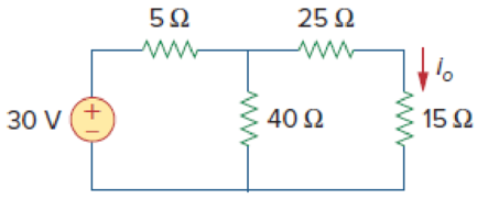
Chapter 4, Problem 1P
Calculate the current io in the circuit of Fig. 4.69. What value of input voltage is necessary to make io equal to 5 amps?
Expert Solution & Answer
Want to see the full answer?
Check out a sample textbook solution
Students have asked these similar questions
*4.45. Determine the operating point and the
small-signal model of Q1 for each of
the circuits shown in Fig. 4.76. Assume
Is = 3 x 10-17 A, B = 100, and VA = 00.
%3D
Rc 1 kQ
+
-Vcc= 2.5 V
Question 4
Figure Q4a shows a basic current mirror structure (in its
'sink' form) which is designed to provide the current Ir at
its output Io by operating transistors Ti and T2 identically :
VDD
IR
IR
T3
T1
T2
T1
T2
OV
OV
Figure Q4a : Current Mirror
Figure Q4b : Widlaw Mirror
a)
Show that the current relationship of the circuit in figure Q4a is
( where Ic = BIb for both transistors and T1 and T2 are matched) :
IR
2
=|1+
If the two transistors in figure Q4a are not matched in terms of
b)
their Vbe's compensation can be provided by placing a resistor 'R'
in one of the emitter legs of the transistors.
Assuming Vbez > Vbel by 0.05V and Ir = Io = 10mA sketch an
appropriate structure and value for R.
c)
Describe how the 'offset' compensation referred to in Q4b
occurs in practice for a 741 op-amp ?
d)
Sketch the 'Source' form of figure Q4a
e)
Figure Q4b shows the buffered Widlar mirror. Briefly
describe how the addition of transistor T3 improves operation.
Construct circuits that produce x'(y'+z')'
Chapter 4 Solutions
Fundamentals of Electric Circuits
Ch. 4.2 - Figure 4.3 For Practice Prob. 4.1. For the circuit...Ch. 4.2 - Figure 4.5 For Practice Prob. 4.2. Assume that Vo...Ch. 4.3 - Figure 4.8 Using the superposition theorem, find...Ch. 4.3 - Figure 4.11 Use superposition to find vx in the...Ch. 4.3 - Find I in the circuit of Fig. 4.14 using the...Ch. 4.4 - Find io in the circuit of Fig. 4.19 using source...Ch. 4.4 - Use source transformation to find ix in the...Ch. 4.5 - Using Thevenins theorem, find the equivalent...Ch. 4.5 - Find the Thevenin equivalent circuit of the...Ch. 4.5 - Obtain the Thevenin equivalent of the circuit in...
Ch. 4.6 - Find the Norton equivalent circuit for the circuit...Ch. 4.6 - Find the Norton equivalent circuit of the circuit...Ch. 4.8 - Determine the value of RL that will draw the...Ch. 4.9 - Rework Practice Prob. 4.9 using PSpice. Find the...Ch. 4.9 - Fin d the maximum power transferred to RL if the...Ch. 4.10 - The measured open-circuit voltage across a certain...Ch. 4.10 - Prob. 17PPCh. 4.10 - Obtain the current through the galvanometer,...Ch. 4 - The current through a branch in a linear network...Ch. 4 - For superposition, it is not required that only...Ch. 4 - The superposition principle applies to power...Ch. 4 - Refer to Fig. 4.67. The Thevenin resistance at...Ch. 4 - The Thevenin voltage across terminals a and b of...Ch. 4 - The Norton current at terminals a and b of the...Ch. 4 - The Norton resistance RN is exactly equal to the...Ch. 4 - Which pair of circuits in Fig. 4.68 are...Ch. 4 - A load is connected to a network. At the terminals...Ch. 4 - The source is supplying the maximum power to the...Ch. 4 - Calculate the current io in the circuit of Fig....Ch. 4 - Using Fig. 4.70, design a problem to help other...Ch. 4 - (a) In the circuit of Fig. 4.71, calculate vo and...Ch. 4 - Use linearity to determine io in the circuit of...Ch. 4 - For the circuit in Fig. 4.73, assume vo = 1 V, and...Ch. 4 - For the linear circuit shown in Fig. 4.74, use...Ch. 4 - Use linearity and the assumption that Vo = 1 V to...Ch. 4 - Using superposition, find Vo in the circuit of...Ch. 4 - Given that I = 6 amps when Vs = 160 volts and Is =...Ch. 4 - Using Fig. 4.78, design a problem to help other...Ch. 4 - Use the superposition principle to find io and vo...Ch. 4 - Determine vo in the circuit of Fig. 4.80 using the...Ch. 4 - Use superposition to find vo in the circuit of...Ch. 4 - Apply the superposition principle to find vo in...Ch. 4 - For the circuit in Fig. 4.83, use superposition to...Ch. 4 - Given the circuit in Fig. 4.84, use superposition...Ch. 4 - Use superposition to obtain vx in the circuit of...Ch. 4 - Use superposition to find Vo in the circuit of...Ch. 4 - Use superposition to solve for vx in the circuit...Ch. 4 - Use source transformation to reduce the circuit...Ch. 4 - Using Fig. 4.89, design a problem to help other...Ch. 4 - For the circuit in Fig, 4.90, use source...Ch. 4 - Referring to Fig. 4.91, use source transformation...Ch. 4 - Use source transformation to find the voltage Vx...Ch. 4 - Obtain vo in the circuit of Fig. 4.93 using source...Ch. 4 - Use source transformation to find io in the...Ch. 4 - Apply source transformation to find vx in the...Ch. 4 - Use source transformation to find Io in Fig. 4.96....Ch. 4 - Use source transformation to find vo in the...Ch. 4 - Use source transformation on the circuit shown in...Ch. 4 - Determine vx in the circuit of Fig. 4.99 using...Ch. 4 - Use source transformation to find ix in the...Ch. 4 - Determine the Thevenin equivalent circuit, shown...Ch. 4 - Using Fig. 4.102, design a problem that will help...Ch. 4 - Use Thevenins theorem to find vo in Prob. 4.12....Ch. 4 - Solve for the current i in the circuit of Fig....Ch. 4 - Find the Norton equivalent with respect to...Ch. 4 - Apply Thevenins theorem to find Vo in the circuit...Ch. 4 - Obtain the Thevenin equivalent at terminals a-b of...Ch. 4 - Find the Thevenin equivalent at terminals a-b of...Ch. 4 - Find the Thevenin and Norton equivalents at...Ch. 4 - For the circuit in Fig. 4.109, find the Thevenin...Ch. 4 - Find the Thevenin equivalent looking into...Ch. 4 - For the circuit in Fig. 4.111, obtain the Thevenin...Ch. 4 - Find the Thevenin equivalent of the circuit in...Ch. 4 - Using Fig. 4.113, design a problem to help other...Ch. 4 - Obtain the Thevenin and Norton equivalent circuits...Ch. 4 - Determine the Norton equivalent at terminals a-b...Ch. 4 - Find the Norton equivalent looking into terminals...Ch. 4 - Obtain the Norton equivalent of the circuit in...Ch. 4 - Given the circuit in Fig. 4.117, obtain the Norton...Ch. 4 - For the transistor model in Fig. 4.118, obtain the...Ch. 4 - Find the Norton equivalent at terminals a-b of the...Ch. 4 - Find the Thevenin equivalent between terminals a-b...Ch. 4 - Obtain the Norton equivalent at terminals a-b of...Ch. 4 - Use Nortons theorem to find Vo in the circuit of...Ch. 4 - Obtain the Thevenin and Norton equivalent circuits...Ch. 4 - The network in Fig. 4.124 models a bipolar...Ch. 4 - Determine the Thevenin and Norton equivalents at...Ch. 4 - For the circuit in Fig. 4.126, find the Thevenin...Ch. 4 - Obtain the Thevenin and Norton equivalent circuits...Ch. 4 - Find the Thevenin equivalent of the circuit in...Ch. 4 - Find the Norton equivalent for the circuit in Fig....Ch. 4 - Obtain the Thevenin equivalent seen at terminals...Ch. 4 - For the circuit shown in Fig. 4.131, determine the...Ch. 4 - Find the maximum power that can be delivered to...Ch. 4 - The variable resistor R in Fig. 4.133 is adjusted...Ch. 4 - Consider the 30- resistor in Fig. 4.134. First...Ch. 4 - Find the maximum power transferred to resistor R...Ch. 4 - Determine the maximum power delivered to the...Ch. 4 - For the circuit in Fig. 4.137, what resistor...Ch. 4 - (a) For the circuit in Fig. 4.138, obtain the...Ch. 4 - Determine the maximum power that can be delivered...Ch. 4 - For the bridge circuit shown in Fig. 4.140, find...Ch. 4 - For the circuit in Fig. 4.141, determine the value...Ch. 4 - Solve Prob. 4.34 using PSpice or MultiSim. Let V =...Ch. 4 - Use PSpice or MultiSim to solve Prob. 4.44. For...Ch. 4 - Use PSpice or MultiSim to solve Prob. 4.52.Ch. 4 - Obtain the Thevenin equivalent of the circuit in...Ch. 4 - Use PSpice or MultiSim to find the Thevenin...Ch. 4 - For the circuit in Fig. 4.126, use PSpice or...Ch. 4 - An automobile battery has an open circuit voltage...Ch. 4 - The following results were obtained from...Ch. 4 - When connected to a 4- resistor, a battery has a...Ch. 4 - The Thevenin equivalent at terminals a-b of the...Ch. 4 - A black box with a circuit in it is connected to a...Ch. 4 - A transducer is modeled with a current source Is...Ch. 4 - Consider the circuit in Fig. 4.144. An ammeter...Ch. 4 - Consider the circuit in Fig. 4.145. (a) Replace...Ch. 4 - The Wheatstone bridge circuit shown in Fig. 4.146...Ch. 4 - (a) In the Wheatstone bridge circuit of Fig. 4.147...Ch. 4 - Consider the bridge circuit of Fig. 4.148. Is the...Ch. 4 - The circuit in Fig. 4.149 models a common-emitter...Ch. 4 - An attenuator is an interface circuit that reduces...Ch. 4 - A dc voltmeter with a sensitivity of 10 k/V is...Ch. 4 - A resistance array is connected to a load resistor...Ch. 4 - A common-emitter amplifier circuit is shown in...Ch. 4 - For Practice Prob. 4.18, determine the current...
Knowledge Booster


Learn more about
Need a deep-dive on the concept behind this application? Look no further. Learn more about this topic, electrical-engineering and related others by exploring similar questions and additional content below.Similar questions
- Q4. An instrumentation industry manufactures the instruments as shown below, if you have to purchase them, then how do you choose them based on time invariant qualities? Analyze them in detail. Meter 1 Meter 2 Meter 3 15 10 AMPERES 20 100 200 300 400 DAGATRON GETO Meter 4 Meter 5arrow_forward*4.45. Determine the operating point and the small-signal model of Q1 for each of the circuits shown in Fig. 4.76. Assume Is = 3 x 10-17 A, B = 100, and VA = 0. 5 k2 Vc" 2.5 V (b)arrow_forwardMT.Q4 - Assuming this clamper circuit uses a silicon diode (VD = 0,7V) in the figure. Determine diode voltage range for ON-OFF situation, calculate and sketch the graphics of output voltage Vo. Vi C 2.1 µF HE 2.5 V Si R ' 56 ΚΩ Vi (V) 201 10- 0 -10 -20 + Vo(V) 0arrow_forward
- In a dual slope integrating type digital voltmeter the first integration is carried out for 5 periods of the supply fre- quency of 50 Hz. If the reference voltage used is 5V, the total conversion time for an input of IV isarrow_forwardIn Resistive Transducer principle the resistance of a resistive element can be varied by several methods. Select one: True Falsearrow_forward1. The 10M resistor (all resistor values are in Ohms and M = million) represents a scope input resistance. Calculate the voltage across the 2M resistor and compare (% error) to the ideal case. An ideal scope input resistance is the same as an ideal internal resistance of a voltmeter. 15V dc 100k 2M 10M Replace the 2M resistor with a 100K resistor and calculate the voltage across the 100K resistor and compare (% error) to the ideal case. For which resistor value (2M or 100K) does the scope have the greatest “loading” effect? Justify your answer.arrow_forward
- Question 11 For the following circuit, as we increase the load resistance R, the diode current Ip increases. Ip + Vo- Vs 多RL True False A Moving to another question will save this response. 3. Ask me anything. DELLarrow_forwardWhat is wrong with this circuit? * = 1N4744A | | 4.790 |V 15V = The zener is open. The zener is shorted or damaged not enough data reversed connection of zener diode O O O Oarrow_forward4.38. A simple voltage-divider circuit is used to measure the output of a transducer whose total resistance is 1000 2+1 percent. The internal resistance of the volt- meter is 10,000 2±5 percent, and the meter is calibrated to read within percent of the true voltage at a full scale of 30 V. The source voltage is 24 V Í 0.05 V. Calculate the percent full-scale reading of the transducer for voltage readings of 6, 12, 18, and 24 V. Estimate the uncertainty for each of these readings. 4.39. Suppose the transducer of Prob. 4.38 is connected to an end resistor of 500 2, as shown in Prob. 4.17. Calculate the percent full-scale reading of the transducer for voltage readings of 12, 15, 18, and 24 V. Estimate the uncertainty for each of these readings, assuming the end resistor is accurate within 1 percent.arrow_forward
- Determine the dc resistance at -10 V. 1 'o(mA) 30- -Silicon 20 10- -10 V 2--- 0.5 I HA 0.8 Vp (V)arrow_forwardQ4. Determine the value of the base resistor () and the load resistor () in the circuit shown in Figure 3. The = 8 V and = 2 mA. The base-emitter voltage = 0.7 V. Vcc 15 V Ic Rc RD 10 µF Vi AH 10 μΕ ß = 100 Figure 3arrow_forwardI. Instructions: Determine the indicated parameters from the given circuits and show the complete solutions. Box your final answer. 1. Determine the Quiescent value of collector current (Icq) and collector voltage (Vceq). 10 V 4.7 k2 250 k2 10 µF B -90 10 µF 1.2 k2arrow_forward
arrow_back_ios
SEE MORE QUESTIONS
arrow_forward_ios
Recommended textbooks for you
 Introductory Circuit Analysis (13th Edition)Electrical EngineeringISBN:9780133923605Author:Robert L. BoylestadPublisher:PEARSON
 Delmar's Standard Textbook Of ElectricityElectrical EngineeringISBN:9781337900348Author:Stephen L. HermanPublisher:Cengage Learning
 Programmable Logic ControllersElectrical EngineeringISBN:9780073373843Author:Frank D. PetruzellaPublisher:McGraw-Hill Education
 Fundamentals of Electric CircuitsElectrical EngineeringISBN:9780078028229Author:Charles K Alexander, Matthew SadikuPublisher:McGraw-Hill Education
 Electric Circuits. (11th Edition)Electrical EngineeringISBN:9780134746968Author:James W. Nilsson, Susan RiedelPublisher:PEARSON
 Engineering ElectromagneticsElectrical EngineeringISBN:9780078028151Author:Hayt, William H. (william Hart), Jr, BUCK, John A.Publisher:Mcgraw-hill Education,
Introductory Circuit Analysis (13th Edition)
Electrical Engineering
ISBN:9780133923605
Author:Robert L. Boylestad
Publisher:PEARSON
Delmar's Standard Textbook Of Electricity
Electrical Engineering
ISBN:9781337900348
Author:Stephen L. Herman
Publisher:Cengage Learning
Programmable Logic Controllers
Electrical Engineering
ISBN:9780073373843
Author:Frank D. Petruzella
Publisher:McGraw-Hill Education
Fundamentals of Electric Circuits
Electrical Engineering
ISBN:9780078028229
Author:Charles K Alexander, Matthew Sadiku
Publisher:McGraw-Hill Education
Electric Circuits. (11th Edition)
Electrical Engineering
ISBN:9780134746968
Author:James W. Nilsson, Susan Riedel
Publisher:PEARSON
Engineering Electromagnetics
Electrical Engineering
ISBN:9780078028151
Author:Hayt, William H. (william Hart), Jr, BUCK, John A.
Publisher:Mcgraw-hill Education,
Norton's Theorem and Thevenin's Theorem - Electrical Circuit Analysis; Author: The Organic Chemistry Tutor;https://www.youtube.com/watch?v=-kkvqr1wSwA;License: Standard Youtube License