
Mechanics of Materials
11th Edition
ISBN: 9780137605460
Author: Russell C. Hibbeler
Publisher: Pearson Education (US)
expand_more
expand_more
format_list_bulleted
Concept explainers
Videos
Textbook Question
Chapter 3.7, Problem 13FP
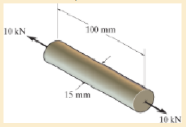
A 100-mm-long rod has a diameter of 15 mm. If an axial tensile load of 10 kN is applied to it, determine the change in its diameter E = 70 GPa, v = 0.35.
Expert Solution & Answer

Learn your wayIncludes step-by-step video

schedule05:27
Students have asked these similar questions
Before the load is placed on the rigid plate, the top of the central spring is 20 mm lower than the outer springs. Each outer spring is made of 24 turns of 15-mm diameter wire on a mean radius of 60 mm. The central spring consists of 16 turns of 20 mm dimeter wire on a mean radius of 80 mm. If a load P = 5 kN is now placed on the rigid plate. Disregarding the weight of the plate, use G = 83 GPa and use Light spring formula. Determine the maximum shearing stress of the in uter spring. In MPa
The stress–strain diagram of the material can be approximated by the two line segments. If a bar having a diameter of 80 mm and a length of 1.5 m is made from this material, determine the critical load provided the ends arepinned. Assume that the load acts through the axis of the bar. Use Engesser’s equation.
The plastic 50-mm diameter rod is placed in a 51-mm-diameter hole with rigid walls. Determine the change in the length of the rod after the 8 kN load is applied. Use E = 40 MPa and v=0.45 for the rod.
Chapter 3 Solutions
Mechanics of Materials
Ch. 3.4 - Define a homogeneous material.Ch. 3.4 - Indicate the points on the stress-strain diagram...Ch. 3.4 - Define the modulus of elasticity E.Ch. 3.4 - At room temperature, mild steel is a ductile...Ch. 3.4 - Engineering stress and strain are calculated using...Ch. 3.4 - As the temperature increases the modulus of...Ch. 3.4 - A 100-mm-long rod has a diameter of 15 mm. If an...Ch. 3.4 - A bar has a length of 8 in. and cross-sectional...Ch. 3.4 - A 10-mm-diameter rod has a modulus of elasticity...Ch. 3.4 - The material for the 50-mm-long specimen has the...
Ch. 3.4 - The material for the 50-mm-long specimen has the...Ch. 3.4 - If the elongation of wire BC is 0.2 mm after the...Ch. 3.4 - Data taken from a stress-strain test for a ceramic...Ch. 3.4 - The stress-strain diagram for a steel alloy having...Ch. 3.4 - The stress-strain diagram for a steel alloy having...Ch. 3.4 - The stress-strain diagram for a steel alloy having...Ch. 3.4 - Determine the elongation of the square hollow bar...Ch. 3.4 - The stress-strain diagram for an aluminum alloy...Ch. 3.4 - The stress-strain diagram for an aluminum alloy...Ch. 3.4 - The stress-strain diagram for an aluminum alloy...Ch. 3.4 - A structural member in a nuclear reactor is made...Ch. 3.4 - The rigid pipe is supported by a pin at A and an...Ch. 3.4 - The rigid pipe is supported by a pin at A and an...Ch. 3.4 - Direct tension indicators are sometimes used...Ch. 3.4 - A tension test was performed on a magnesium alloy...Ch. 3.4 - The stress-strain diagram for a bone is shown and...Ch. 3.4 - The two bars are made of a material that has the...Ch. 3.4 - The two bars are made of a material that has the...Ch. 3.7 - A 100-mm-long rod has a diameter of 15 mm. If an...Ch. 3.7 - A solid circular rod that is 600 mm long and 20 mm...Ch. 3.7 - A 20-mm-wide block is firmly bonded to rigid...Ch. 3.7 - A 20-mm-wide block is bonded to rigid plates at...Ch. 3.7 - The acrylic plastic rod is 400mm long and 20mm in...Ch. 3.7 - The elastic portion of the stress-strain diagram...Ch. 3.7 - The elastic portion of the stress-strain diagram...Ch. 3.7 - The lap joint is connected together using a 1.25...Ch. 3.7 - The lap joint is connected together using a 1.25...Ch. 3.7 - Prob. 32PCh. 3.7 - The thin-walled tube is subjected to an axial...Ch. 3 - The elastic portion of the tension stress-strain...Ch. 3 - The elastic portion of the tension stress-strain...Ch. 3 - The rigid beam rests in the horizontal position on...Ch. 3 - The wires each have a diameter of 12 in., length...Ch. 3 - Prob. 5RPCh. 3 - diameter steel bolts. If the clamping force in...Ch. 3 - The stress-strain diagram for polyethylene, which...Ch. 3 - The pipe with two rigid caps attached to its ends...Ch. 3 - The 8-mm-diameter bolt is made of an aluminum...Ch. 3 - An acetal polymer block is fixed to the rigid...
Additional Engineering Textbook Solutions
Find more solutions based on key concepts
The cantilevered jib crane is used to support the load of 780 lb, if. x = 5 ft. determine the reactions at the ...
Engineering Mechanics: Statics
The force in members BC, CF, and FE of the truss and the state of members are in tension or compression.
Engineering Mechanics: Statics & Dynamics (14th Edition)
Water at 10 C flows at the rate of 900 L/min from the reservoir and through the pipe shown in Fig. 8.16. Comput...
Applied Fluid Mechanics (7th Edition)
Show that for circular motion, force = mass * velocity squared/radius.
Thinking Like an Engineer: An Active Learning Approach (3rd Edition)
What parts are included in the vehicle chassis?
Automotive Technology: Principles, Diagnosis, And Service (6th Edition) (halderman Automotive Series)
In each case, determine the moment of the force about point O. Prob. P3-1
Statics and Mechanics of Materials (5th Edition)
Knowledge Booster


Learn more about
Need a deep-dive on the concept behind this application? Look no further. Learn more about this topic, mechanical-engineering and related others by exploring similar questions and additional content below.Similar questions
- The 304 stainless steel post A is surrounded by a red brass C83400 tube B. Both rest on the rigid surface. If a force of 25 kN is applied to the rigid cap, determine the required diameter d of the steel post so that the load is shared equally between the post and tube. The elastic modulus for brass is 101 GPa and the elastic modulus for steel is 193 GPaarrow_forwardThe stress–strain diagram for a material can be approximated by the two line segments shown. If a bar having a diameter of 80 mm and a length of 1.5 m is made from this material, determine the critical load provided one end is pinned and the other is fixed. Assume that the load acts through the axis of the bar. Use Engesser’s equation.arrow_forwardThe stress–strain diagram for a material can be approximated by the two line segments shown. If a bar having a diameter of 80 mm and a length of 1.5 m is made from this material, determine the critical load provided the ends are pinned. Assume that the load acts through the axis of the bar. Use Engesser’s equation.arrow_forward
- The post has a circular cross section of radius c. Determine the maximum radius e at which the load P can be applied so that no part of the post experiences a tensile stress. Neglect the weight of the post.arrow_forwardThe A-36 steel wire AB has a cross-sectional area of 5 mm2 and is unstretched when θ=45.0∘ Determine the applied load P needed to cause θ= 44.8 ∘. Image is providedarrow_forwardThe ball is truncated at its ends and is used to support the bearing load P. The modulus of elasticity for the material is E. Determine the decrease in the ball's height when the load is applied. Express your answer as an expression in terms of the variables P, r, and E and any necessary constants.arrow_forward
- The acrylic plastic rod is 200 mm long and 15 mm in diameter. If an axial load of 300 N is applied to it, determine the change in its length and the change in its diameter. Ep = 2.70 GPa, np = 0.4.arrow_forwardThe steel pipe is fixed supported at its ends. If it is 4 m long and has an outer diameter of 50 mm, determine its required thickness so that it can support an axial load of P = 100 kN without buckling. Est = 200 GPa, sY = 250 MPa.arrow_forwardA steel column is of length 8m and diameter 600 mm with both ends hinged.Determine the crippling load by Euler’s formula. Take 5 E = 2.1x10 N/mm2arrow_forward
- The rigid pipe is supported by a pin at A and an A-36 guy wire BD. If the wire has a diameter of 0.25 in., determine the load P if the end C is displaced 0.075 in. downward.arrow_forwardThe truss consists of three members, each made from A-36 steel and having a cross-sectional area of 0.75 in2. Determine the greatest load P that can be applied so that the roller support at B is not displaced more than 0.03 in.arrow_forwardAxial loads are applied with rigid bearing plates to the solid cylindrical rods shown. If F1 = 31 kips, F2 = 15 kips, F3 = 26 kips, and F4 = 39 kips, determine the absolute value of the axial load in rod (2).arrow_forward
arrow_back_ios
SEE MORE QUESTIONS
arrow_forward_ios
Recommended textbooks for you
 Elements Of ElectromagneticsMechanical EngineeringISBN:9780190698614Author:Sadiku, Matthew N. O.Publisher:Oxford University Press
 Mechanics of Materials (10th Edition)Mechanical EngineeringISBN:9780134319650Author:Russell C. HibbelerPublisher:PEARSON
 Thermodynamics: An Engineering ApproachMechanical EngineeringISBN:9781259822674Author:Yunus A. Cengel Dr., Michael A. BolesPublisher:McGraw-Hill Education
 Control Systems EngineeringMechanical EngineeringISBN:9781118170519Author:Norman S. NisePublisher:WILEY
 Mechanics of Materials (MindTap Course List)Mechanical EngineeringISBN:9781337093347Author:Barry J. Goodno, James M. GerePublisher:Cengage Learning
 Engineering Mechanics: StaticsMechanical EngineeringISBN:9781118807330Author:James L. Meriam, L. G. Kraige, J. N. BoltonPublisher:WILEY
Elements Of Electromagnetics
Mechanical Engineering
ISBN:9780190698614
Author:Sadiku, Matthew N. O.
Publisher:Oxford University Press
Mechanics of Materials (10th Edition)
Mechanical Engineering
ISBN:9780134319650
Author:Russell C. Hibbeler
Publisher:PEARSON
Thermodynamics: An Engineering Approach
Mechanical Engineering
ISBN:9781259822674
Author:Yunus A. Cengel Dr., Michael A. Boles
Publisher:McGraw-Hill Education
Control Systems Engineering
Mechanical Engineering
ISBN:9781118170519
Author:Norman S. Nise
Publisher:WILEY
Mechanics of Materials (MindTap Course List)
Mechanical Engineering
ISBN:9781337093347
Author:Barry J. Goodno, James M. Gere
Publisher:Cengage Learning
Engineering Mechanics: Statics
Mechanical Engineering
ISBN:9781118807330
Author:James L. Meriam, L. G. Kraige, J. N. Bolton
Publisher:WILEY
EVERYTHING on Axial Loading Normal Stress in 10 MINUTES - Mechanics of Materials; Author: Less Boring Lectures;https://www.youtube.com/watch?v=jQ-fNqZWrNg;License: Standard YouTube License, CC-BY