Physics for Scientists and Engineers: A Strategic Approach, Vol. 1 (Chs 1-21) (4th Edition)
4th Edition
ISBN: 9780134110684
Author: Randall D. Knight (Professor Emeritus)
Publisher: PEARSON
expand_more
expand_more
format_list_bulleted
Videos
Textbook Question
Chapter 30, Problem 66EAP
FIGURE P30.66 shows the current through a
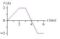
FIGURE P30.66
Expert Solution & Answer
Want to see the full answer?
Check out a sample textbook solution
Students have asked these similar questions
W
R₂
a
a. What is the potential drop on the inductor?
R₁
m
Two resistors, R₁ = 125 § and R2 = 325 92, an inductor L = 3.7 mH, a 16 V battery, and a switch are connected as shown above. The switch has been in position a for a long time.
What is the current through resistor R₁?
What is the current through resistor R₂?
Submit Answer Tries 0/10
L
b. At time t = 0s the switch is moved to position b. What is the time constant of the RL circuit obtained?
Submit Answer Tries 0/10
c. Find the current in this RL circuit when the time t is three-quarters of the time constant from part b.
Submit Answer Tries 0/10
d. At what time has the current decayed to 0.75% of its initial value?
Submit Answer Tries 0/10
At t=infinity, what is the current flowing through an inductor?
What is the voltage across the inductor at t=0?
At t=infinity, what is the voltage across the inductor?
A resistor of resistance R = 10 Ω is connected in series with an inductor of L = 15 mH. The RL combination is connected to a variable voltage power supply (V = 4.5 V) by a switch as shown.
a. What is the time constant (τ) of the combination in seconds?
b. The power supply is set to maintain a constant voltage of V = 4.5 V and the switch is closed. Calculate the current, in amperes, through the circuit at t = 0.29 ms after the switch is closed.
c. Calculate the current through the circuit, in amperes, after the switch has been closed for a long time.
Chapter 30 Solutions
Physics for Scientists and Engineers: A Strategic Approach, Vol. 1 (Chs 1-21) (4th Edition)
Ch. 30 - Prob. 1CQCh. 30 - You want to insert a loop of copper wire between...Ch. 30 - A vertical, rectangular loop of copper wire is...Ch. 30 - Does the loop of wire in FIGURE Q30.4 have a...Ch. 30 - s5. The two loops of wire in FIGURE Q30.5 are...Ch. 30 - FIGURE Q30.6 shows a bar magnet being pushed...Ch. 30 - A bar magnet is pushed toward a loop of wire as...Ch. 30 - FIGURE Q30.8 shows a bar magnet. a coil of wire,...Ch. 30 - Prob. 9CQCh. 30 - An inductor with a 2.0 A current stores energy. At...
Ch. 30 - Prob. 11CQCh. 30 - Prob. 12CQCh. 30 - Rank in order, from largest to smallest, the three...Ch. 30 - For the circuit of FIGURE Q30.14: a. What is the...Ch. 30 - The earth’s magnetic field strength is 5.0105T ....Ch. 30 - A potential difference of 0.050 V is developed...Ch. 30 - A 10 -cm-long wire is pulled along a U-shaped...Ch. 30 - What is the magnetic flux through the loop shown...Ch. 30 - FIGURE EX30.5 shows a 10cm10cm square bent at a 90...Ch. 30 - Prob. 6EAPCh. 30 - Prob. 7EAPCh. 30 - FIGURE EX30.8 shows a 2.0 -cm-diameter solenoid...Ch. 30 - Prob. 9EAPCh. 30 - 10. A solenoid is wound as shown in FIGURE...Ch. 30 - 11. The metal equilateral triangle in FIGURE...Ch. 30 - The current in the solenoid of FIGURE EX3O.12 is...Ch. 30 - The loop in FIGURE EX30.13 is being pushed into...Ch. 30 - FIGURE EX30.14 shows a 10-cm-diameter loop in...Ch. 30 - Prob. 15EAPCh. 30 - 16. A -turn coil of wire cm in diameter is in a...Ch. 30 - A 5.0 -cm-diameter coil has 20 turns and a...Ch. 30 - FIGURE EX30.18 shows the current as a function of...Ch. 30 - The magnetic field in FIGURE EX30.19 is decreasing...Ch. 30 - The magnetic field inside a -cm-diameter solenoid...Ch. 30 - Scientists studying an anomalous magnetic field...Ch. 30 - Prob. 22EAPCh. 30 - Prob. 23EAPCh. 30 - Prob. 24EAPCh. 30 - Prob. 25EAPCh. 30 - Prob. 26EAPCh. 30 - How much energy is stored in a -cm-diameter,...Ch. 30 - MRI (magnetic resonance imaging) is a medical...Ch. 30 - Prob. 29EAPCh. 30 - Prob. 30EAPCh. 30 - Prob. 31EAPCh. 30 - Prob. 32EAPCh. 30 - Prob. 33EAPCh. 30 - Prob. 34EAPCh. 30 - At t=0 s, the current in the circuit in FIGURE...Ch. 30 - The switch in FIGURE EX3O.36 has been open for a...Ch. 30 - Prob. 37EAPCh. 30 - Prob. 38EAPCh. 30 - Prob. 39EAPCh. 30 - Prob. 40EAPCh. 30 - A 10cm10cm square loop lies in the xy-plane. The...Ch. 30 - A spherical balloon with a volume of L is in a mT...Ch. 30 - Prob. 43EAPCh. 30 - Prob. 44EAPCh. 30 - Prob. 45EAPCh. 30 - FIGURE P30.46 shows a 4.0-cm-diameter loop with...Ch. 30 - Prob. 47EAPCh. 30 - Prob. 48EAPCh. 30 - Prob. 49EAPCh. 30 - Prob. 50EAPCh. 30 - Prob. 51EAPCh. 30 - Prob. 52EAPCh. 30 - Prob. 53EAPCh. 30 - Prob. 54EAPCh. 30 - Prob. 55EAPCh. 30 - Your camping buddy has an idea for a light to go...Ch. 30 - 57. The -wide, zero-resistance slide wire shown...Ch. 30 - ]58. You’ve decided to make the magnetic...Ch. 30 - FIGURE P30.59 shows a U-shaped conducting rail...Ch. 30 - Prob. 60EAPCh. 30 - Prob. 61EAPCh. 30 - Prob. 62EAPCh. 30 - Equation 30.26 is an expression for the induced...Ch. 30 - Prob. 64EAPCh. 30 - One possible concern with MRI (see Exercise 28) is...Ch. 30 - FIGURE P30.66 shows the current through a 10mH...Ch. 30 - Prob. 67EAPCh. 30 - Prob. 68EAPCh. 30 - Prob. 69EAPCh. 30 - Prob. 70EAPCh. 30 - An LC circuit is built with a inductor and an...Ch. 30 - Prob. 72EAPCh. 30 - For your final exam in electronics, you’re asked...Ch. 30 - The inductor in FIGURE P30.74 is a -cm-long, -cm-...Ch. 30 - The capacitor in FIGURE P30.75 is initially...Ch. 30 - The switch in FIGURE P30.76 has been open for a...Ch. 30 - 77. The switch in FIGURE P30.77 has been open for...Ch. 30 - Prob. 78EAPCh. 30 - Prob. 79EAPCh. 30 - Prob. 80EAPCh. 30 - In recent years it has been possible to buy a 1.0F...Ch. 30 - Prob. 82EAPCh. 30 - Prob. 83EAPCh. 30 - Prob. 84EAPCh. 30 - A 2.0 -cm-diameter solenoid is wrapped with 1000...Ch. 30 - High-frequency signals are often transmitted along...
Knowledge Booster


Learn more about
Need a deep-dive on the concept behind this application? Look no further. Learn more about this topic, physics and related others by exploring similar questions and additional content below.Similar questions
- Figure CQ20.7 shows a slidewire generator with motional cmf 0 when the wire at A slides across the top and bottom rails at constant velocity v0. (a) When the wire reaches B so that the area enclosed by the circuit is doubled, determine the ratio of the new cmf to the original cmf, /0. (b) If the wire's speed is doubled so that v = 2v0 determine the ratio /0. Figure CQ20.7arrow_forwardThe current I(t) through a 5.0-mH inductor varies with time, as shown below. The resistance of the inductor is 5.0 . Calculate the voltage across the inductor at t = 2.0 ms, r = 4.0 ms, and t = 8.0 ms.arrow_forwardA 70 μF capacitor with a 13 μC charge is connected across a 18 mH inductor. What is the charge on the capacitor and what is the current through the inductor 0.55 ms after the circuit is connected?arrow_forward
- A 6.0 V battery has been connected to an LR circuit for sufficient time so that a steady current flows through the resistor R=2.2kΩ and inductor L=18mH. At t=0, the battery is removed from the circuit and the current decays exponentially through R. Write the equation for the emf across the inductor as a function of time t. At what time is the emf greatest? What is this maximum value (V)?arrow_forwardAn ideal inductor L=100 mH is connected to a source whose peak potential difference is 65 V. a) If the frequency is 60 Hz. what is the current at 8 ms? What is the instantaneous power delivered to the inductor at this time? b) At what frequency would the peak current be 2.5 A?arrow_forwardAn inductor in the form of a solenoid contains 410 turns and is 15.0 cm in length. A uniform rate of decrease of current through the inductor of 0.421 A/s induces an emf of 175 µV. What is the radius of the solenoid? mmarrow_forward
- A 14.0 mH inductor makes the current drop from 178 mA to 66.0 mA in only 10.0 μs. What is the potential difference across the inductor? 0.00157 V -92.4 V -249 V 157 Varrow_forwardThe 4.00 A current through a 1.30 H inductor is dissipated by a 2.00 Ω resistor in a circuit like that in the figure below with the switch in position 2. a. What is the initial energy in the inductor? b. How long will it take the current to decline to 15.00% of its initial value? c. Calculate the average power dissipated in the inductor. d. What is the ratio of the initial power dissipated by the resistor to the average power dissipated by the inductor?arrow_forwardPlease help me with the given question nd make sure its 100% correct, thank you A 24.0 μF capacitor is charged to 195 μC and then connected across the ends of a 4.80 mH inductor. Part A. Find the maximum current in the inductor. Express your answer with the appropriate units. Part B. Find the maximum energy stored in the inductor. Express your answer with the appropriate units. Part C. At the instant the energy stored in the inductor is maximum, what is the current in the circuit? Express your answer with the appropriate units.arrow_forward
- One application of an RL circuit is the generation of time-varying high voltage from a low-voltage source. As shown in the figure below, R1 15.0V. What is the current in the inductor a long time after the switch has been in position A? 1.25 A B E L R₁ w R₁₂ = 103002, R2 = 12.0, L = 1.82H and ε =arrow_forwardTwo inductors are placed in a circuit in series with each other. Inductor 1 has an inductance of 3.5e-3 H and inductor 2 has an inductance of 4.7e-6 H. Anytime current is running through the inductors, what is the ratio of energy stored in inductor 1 compared to inductor 2? U1 is the energy in inductor 1 and U2 is the energy in inductor 2. U1 = 25.36 U2 U1 = 1.55e-3 U2 U1 = 744.68 U2 U1 = 3.93e-2 U2arrow_forwarda L A current I is flowing through an inductor. At time t = time t = 1s the current becomes 1 A. Which of the two points (a or b) has the 0, the current is zero and at higher potential at this time period? Select one: O a. neither a nor b b. point b O c. point aarrow_forward
arrow_back_ios
SEE MORE QUESTIONS
arrow_forward_ios
Recommended textbooks for you

 Physics for Scientists and Engineers, Technology ...PhysicsISBN:9781305116399Author:Raymond A. Serway, John W. JewettPublisher:Cengage Learning
 Principles of Physics: A Calculus-Based TextPhysicsISBN:9781133104261Author:Raymond A. Serway, John W. JewettPublisher:Cengage Learning
 Physics for Scientists and Engineers: Foundations...PhysicsISBN:9781133939146Author:Katz, Debora M.Publisher:Cengage Learning
 College PhysicsPhysicsISBN:9781305952300Author:Raymond A. Serway, Chris VuillePublisher:Cengage Learning
Physics for Scientists and Engineers, Technology ...
Physics
ISBN:9781305116399
Author:Raymond A. Serway, John W. Jewett
Publisher:Cengage Learning
Principles of Physics: A Calculus-Based Text
Physics
ISBN:9781133104261
Author:Raymond A. Serway, John W. Jewett
Publisher:Cengage Learning
Physics for Scientists and Engineers: Foundations...
Physics
ISBN:9781133939146
Author:Katz, Debora M.
Publisher:Cengage Learning
College Physics
Physics
ISBN:9781305952300
Author:Raymond A. Serway, Chris Vuille
Publisher:Cengage Learning
What is Electromagnetic Induction? | Faraday's Laws and Lenz Law | iKen | iKen Edu | iKen App; Author: Iken Edu;https://www.youtube.com/watch?v=3HyORmBip-w;License: Standard YouTube License, CC-BY