Physics for Scientists and Engineers: A Strategic Approach, Vol. 1 (Chs 1-21) (4th Edition)
4th Edition
ISBN: 9780134110684
Author: Randall D. Knight (Professor Emeritus)
Publisher: PEARSON
expand_more
expand_more
format_list_bulleted
Videos
Textbook Question
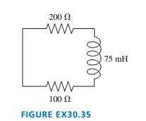
Chapter 30, Problem 35EAP
At
Expert Solution & Answer
Want to see the full answer?
Check out a sample textbook solution
Students have asked these similar questions
For the circuit in the figure, at t = 0 the switch S is closed with the capacitor uncharged. If C = 52 µF, & = 80V, and R = 4 k2, what is the
charge (in m) on the capacitor when the current in the circuit is I = 2.5 mA?
S
R
Select one:
OA 5.56
O B. 2.55
OC.4.13
OD. 4.68
OE. 3.64
The capacitor in the circuit shown is fully charged by a 24 V battery. The switch is closed at t = 0. At sometime after
the switch is closed, the voltage across the capacitor is measured to be 10 V. What is the current in the circuit at
this time, in Ampere? C = 3.0 µF, and R = 2.0 02.
Your answer needs to have 2 significant figures, including the negative sign in your answer if needed. Do not
include the positive sign if the answer is positive. No unit is needed in your answer, it is already given in the
question statement.
Cil
For the circuit in the figure, at t = 0 the switch S is
closed with the capacitor uncharged. If C = 55 µF, ɛ =
80V, and R = 4 kN, what is the charge (in mC) on the
capacitor when the current in the circuit is = 3.5 mA?
S
R
+
Select one:
O A. 5.67
ОВ. 4.15
OC. 5.17
O D. 3.63
E. 2.48
Chapter 30 Solutions
Physics for Scientists and Engineers: A Strategic Approach, Vol. 1 (Chs 1-21) (4th Edition)
Ch. 30 - Prob. 1CQCh. 30 - You want to insert a loop of copper wire between...Ch. 30 - A vertical, rectangular loop of copper wire is...Ch. 30 - Does the loop of wire in FIGURE Q30.4 have a...Ch. 30 - s5. The two loops of wire in FIGURE Q30.5 are...Ch. 30 - FIGURE Q30.6 shows a bar magnet being pushed...Ch. 30 - A bar magnet is pushed toward a loop of wire as...Ch. 30 - FIGURE Q30.8 shows a bar magnet. a coil of wire,...Ch. 30 - Prob. 9CQCh. 30 - An inductor with a 2.0 A current stores energy. At...
Ch. 30 - Prob. 11CQCh. 30 - Prob. 12CQCh. 30 - Rank in order, from largest to smallest, the three...Ch. 30 - For the circuit of FIGURE Q30.14: a. What is the...Ch. 30 - The earth’s magnetic field strength is 5.0105T ....Ch. 30 - A potential difference of 0.050 V is developed...Ch. 30 - A 10 -cm-long wire is pulled along a U-shaped...Ch. 30 - What is the magnetic flux through the loop shown...Ch. 30 - FIGURE EX30.5 shows a 10cm10cm square bent at a 90...Ch. 30 - Prob. 6EAPCh. 30 - Prob. 7EAPCh. 30 - FIGURE EX30.8 shows a 2.0 -cm-diameter solenoid...Ch. 30 - Prob. 9EAPCh. 30 - 10. A solenoid is wound as shown in FIGURE...Ch. 30 - 11. The metal equilateral triangle in FIGURE...Ch. 30 - The current in the solenoid of FIGURE EX3O.12 is...Ch. 30 - The loop in FIGURE EX30.13 is being pushed into...Ch. 30 - FIGURE EX30.14 shows a 10-cm-diameter loop in...Ch. 30 - Prob. 15EAPCh. 30 - 16. A -turn coil of wire cm in diameter is in a...Ch. 30 - A 5.0 -cm-diameter coil has 20 turns and a...Ch. 30 - FIGURE EX30.18 shows the current as a function of...Ch. 30 - The magnetic field in FIGURE EX30.19 is decreasing...Ch. 30 - The magnetic field inside a -cm-diameter solenoid...Ch. 30 - Scientists studying an anomalous magnetic field...Ch. 30 - Prob. 22EAPCh. 30 - Prob. 23EAPCh. 30 - Prob. 24EAPCh. 30 - Prob. 25EAPCh. 30 - Prob. 26EAPCh. 30 - How much energy is stored in a -cm-diameter,...Ch. 30 - MRI (magnetic resonance imaging) is a medical...Ch. 30 - Prob. 29EAPCh. 30 - Prob. 30EAPCh. 30 - Prob. 31EAPCh. 30 - Prob. 32EAPCh. 30 - Prob. 33EAPCh. 30 - Prob. 34EAPCh. 30 - At t=0 s, the current in the circuit in FIGURE...Ch. 30 - The switch in FIGURE EX3O.36 has been open for a...Ch. 30 - Prob. 37EAPCh. 30 - Prob. 38EAPCh. 30 - Prob. 39EAPCh. 30 - Prob. 40EAPCh. 30 - A 10cm10cm square loop lies in the xy-plane. The...Ch. 30 - A spherical balloon with a volume of L is in a mT...Ch. 30 - Prob. 43EAPCh. 30 - Prob. 44EAPCh. 30 - Prob. 45EAPCh. 30 - FIGURE P30.46 shows a 4.0-cm-diameter loop with...Ch. 30 - Prob. 47EAPCh. 30 - Prob. 48EAPCh. 30 - Prob. 49EAPCh. 30 - Prob. 50EAPCh. 30 - Prob. 51EAPCh. 30 - Prob. 52EAPCh. 30 - Prob. 53EAPCh. 30 - Prob. 54EAPCh. 30 - Prob. 55EAPCh. 30 - Your camping buddy has an idea for a light to go...Ch. 30 - 57. The -wide, zero-resistance slide wire shown...Ch. 30 - ]58. You’ve decided to make the magnetic...Ch. 30 - FIGURE P30.59 shows a U-shaped conducting rail...Ch. 30 - Prob. 60EAPCh. 30 - Prob. 61EAPCh. 30 - Prob. 62EAPCh. 30 - Equation 30.26 is an expression for the induced...Ch. 30 - Prob. 64EAPCh. 30 - One possible concern with MRI (see Exercise 28) is...Ch. 30 - FIGURE P30.66 shows the current through a 10mH...Ch. 30 - Prob. 67EAPCh. 30 - Prob. 68EAPCh. 30 - Prob. 69EAPCh. 30 - Prob. 70EAPCh. 30 - An LC circuit is built with a inductor and an...Ch. 30 - Prob. 72EAPCh. 30 - For your final exam in electronics, you’re asked...Ch. 30 - The inductor in FIGURE P30.74 is a -cm-long, -cm-...Ch. 30 - The capacitor in FIGURE P30.75 is initially...Ch. 30 - The switch in FIGURE P30.76 has been open for a...Ch. 30 - 77. The switch in FIGURE P30.77 has been open for...Ch. 30 - Prob. 78EAPCh. 30 - Prob. 79EAPCh. 30 - Prob. 80EAPCh. 30 - In recent years it has been possible to buy a 1.0F...Ch. 30 - Prob. 82EAPCh. 30 - Prob. 83EAPCh. 30 - Prob. 84EAPCh. 30 - A 2.0 -cm-diameter solenoid is wrapped with 1000...Ch. 30 - High-frequency signals are often transmitted along...
Knowledge Booster


Learn more about
Need a deep-dive on the concept behind this application? Look no further. Learn more about this topic, physics and related others by exploring similar questions and additional content below.Similar questions
- In the circuit shown in the figure, Rị = 20.0 N, R2 = 30.0 N, R3 = 40.0 N, L = 15.0 H %3D and e = 100 V. What is the current i in units of ampere at t = 0.700 s after the switch is closed. R1 R3 R2 000arrow_forwardThe current in a single-loop circuit with one resistance R is 5.8 A. When an additional resistance of 1.9 2 is inserted in series with R, the current drops to 5.1 A. What is R? Number i Units +arrow_forwardS 3. For the circuit shown to the right, the resistance is 4,000 Ohms, the capacitance is 100x10-6 F, and the battery is 30 V. + C a. What is the time constant for the circuit?. b. What is the current in the circuit at t = 0 and t = infinity? c. What is the current in the circuit as a function of time?arrow_forward
- The capacitor in the circuit shown below is initially uncharged. The switch is closed at t = 0 s. AVbattery = 24 V, C = 3.0 μF, and R = 2.0 Q. At sometime after the switch is closed, the voltage across the capacitor is measured to be 10 V. What is the current in the circuit at this time, in Ampere? Your answer needs to have 2 significant figures, including the negative sign in your answer if needed. Do not include the positive sign if the answer is positive. No unit is needed in your answer, it is already given in the question statement.arrow_forwardYou connect a battery, resistor, and capacitor as in (Figure 1), where R = 14.0 Ω and C = 3.00 ×10^-6 F. The switch S is closed at t = 0. When the current in the circuit has magnitude 3.00 A, the charge on the capacitor is 40.0 × 10^−6 C. At what time t after the switch is closed is the charge on the capacitor equal to 40.0 x 10^-6 C? When the current has magnitude 3.00 A, at what rate is energy being stored in the capacitor?arrow_forwardThere is a current of 0.25 A in the circuit of Figure P23.69.a. What is the direction of the current? Explain.b. What is the value of the resistance R?c. What is the power dissipated by R?d. Make a graph of potential versus position, starting from V = 0 V in the lower left corner and proceeding clockwise.See Figure P23.9 for an example.arrow_forward
- The capacitor in the circuit shown below is initially uncharged. The switch is closed at t = 0 s. AV battery = 30 V, C = 3.0 F, and R = 2.0 2. At sometime after the switch is closed, the current in the circuit is measured to be 9.3 A. What is the charge on the capacitor at this time, in Coulomb? Your answer needs to have 2 significant figures, including the negative sign in your answer if needed. Do not include the positive sign if the answer is positive. No unit is needed in your answer, it is already given in the question statement.arrow_forwardA generator produces 250 kW of electric power at 7.2 kV. The current is transmitted to a remote village through wires with a total resistance of 15 Ω.a. What is the power loss due to resistance in the wires?b. What is the power loss if the voltage is increased to 30 kV?arrow_forwardA 1·21-MF Capacitor is connected to a North American electrical outlet. (Avrms = 120V, f = 60·0Hz). Assuming energy stored in the Capacitor is Zero at + = 0, determine the magnitude & the current in the wires at t = 192 Note 3 Answer must be in A. S thearrow_forward
- Copper has a resistivity of ρc = 1.72 × 10⁻⁸ Ω⋅m. An extension cord made of copper is connected to a DC electric motor which requires a current of at least Imin = 4.5 A in order to operate. The cord is connected to a V = 151 V source. A. Input an expression for the maximum ratio of length to cross-sectional area, γ, the cord can have if the motor is to operate. B. What is the ratio numerically in 1/m? C. Experimentally, it is found that the maximum length the cord can be is Lmax = 30 m. What is the wire's minimum diameter, Dmin, in meters?arrow_forwardChapter 32, Problem 018 Your answer is partially correct. Try again. The circuit in the figure consists of switch S, a 4.50 V ideal battery, a 35.0 M2 resistor, and an airfilled capacitor. The capacitor has parallel circular plates of radius 5.10 cm, separated by 1.50 mm. At time t = 0, switch S is closed to begin charging the capacitor. The electric field between the plates is uniform. At t = 160 µs, what is the magnitude of the magnetic field within the capacitor, at radial distance 3.30 cm? C S R Number Units T. Use correct number of significant digits; the tolerance is +/-1 in the 3rd significant digitarrow_forwardChapter 32, Problem 018 Your answer is partially correct. Try again. The circuit in the figure consists of switch S, a 4.50 V ideal battery, a 35.0 M2 resistor, and an airfilled capacitor. The capacitor has parallel circular plates of radius 5.10 cm, separated by 1.50 mm. At time t = 0, switch S is closed to begin charging the capacitor. The electric field between the plates is uniform. At t = 160 µs, what is the magnitude of the magnetic field within the capacitor, at radial distance 3.30 cm? S R Number Units Use correct number of significant digits; the tolerance is +/-1 in the 3rd significant digitarrow_forward
arrow_back_ios
SEE MORE QUESTIONS
arrow_forward_ios
Recommended textbooks for you
 Physics for Scientists and Engineers: Foundations...PhysicsISBN:9781133939146Author:Katz, Debora M.Publisher:Cengage Learning
 Principles of Physics: A Calculus-Based TextPhysicsISBN:9781133104261Author:Raymond A. Serway, John W. JewettPublisher:Cengage Learning
 Physics for Scientists and EngineersPhysicsISBN:9781337553278Author:Raymond A. Serway, John W. JewettPublisher:Cengage Learning
 Physics for Scientists and Engineers with Modern ...PhysicsISBN:9781337553292Author:Raymond A. Serway, John W. JewettPublisher:Cengage Learning
Physics for Scientists and Engineers: Foundations...
Physics
ISBN:9781133939146
Author:Katz, Debora M.
Publisher:Cengage Learning
Principles of Physics: A Calculus-Based Text
Physics
ISBN:9781133104261
Author:Raymond A. Serway, John W. Jewett
Publisher:Cengage Learning
Physics for Scientists and Engineers
Physics
ISBN:9781337553278
Author:Raymond A. Serway, John W. Jewett
Publisher:Cengage Learning
Physics for Scientists and Engineers with Modern ...
Physics
ISBN:9781337553292
Author:Raymond A. Serway, John W. Jewett
Publisher:Cengage Learning
What is Electromagnetic Induction? | Faraday's Laws and Lenz Law | iKen | iKen Edu | iKen App; Author: Iken Edu;https://www.youtube.com/watch?v=3HyORmBip-w;License: Standard YouTube License, CC-BY