
DESIGN OF MACHINERY
6th Edition
ISBN: 9781260113310
Author: Norton
Publisher: RENT MCG
expand_more
expand_more
format_list_bulleted
Concept explainers
Videos
Textbook Question
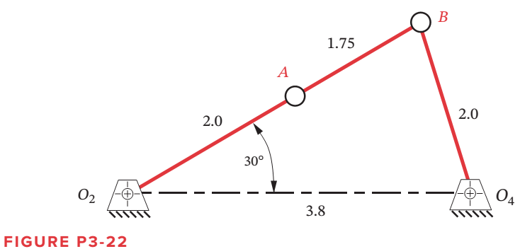
Chapter 3, Problem 3.93P
Figure P3-22 shows a non-Grashof fourbar linkage that is driven from link
(a) Find the transmission angle at the position shown.
(b) Find the toggle positions in terms of angle
Expert Solution & Answer
Want to see the full answer?
Check out a sample textbook solution
Students have asked these similar questions
Plz answer this question
Given the vectors in Figure P1-2 using a scale of 1 inch = 10 units, and determine the following vectors on the image below:
Additional information
A= 20
B= 270⁰ ; 10
C=210⁰ ; 15
D=315⁰; 12,5
E=75⁰ ; 7,5
F=215⁰ ; 10
G=100⁰ ; 15
Figure p3-31 the only problem I want to sol
B3. SOLVE STEP BY STEP IN DIGITAL FORMAT
A set of sprockets is constructed, as shown in Figure 1, so that the second and third rotate
on a common axis. When the first rotates, it drives the second and this in turn drives the
third. Let and be the numbers of revolutions per minute of the first, second, and third axes.
dy du
dy dy dtu
Find
www.du' dx'
and, and verify that
dr
du
Figure 1
|1cm
axis 1
|- 4cm -|
axis 2
axis 1: y rev per minute
axis 2: u rev per minute
axis 3: x rev per minute
|1e|
|- 3cm-||
axis 3
Chapter 3 Solutions
DESIGN OF MACHINERY
Ch. 3 - Define the following examples as path, motion, or...Ch. 3 - Design a fourbar Grashof crank-rocker for 90 of...Ch. 3 - Prob. 3.3PCh. 3 - Design a fourbar mechanism to give the two...Ch. 3 - Prob. 3.5PCh. 3 - Prob. 3.6PCh. 3 - Repeat Problem 3-2 with a quick-return time ratio...Ch. 3 - Design a sixbar drag link quick-return linkage for...Ch. 3 - Design a crank-shaper quick-return mechanism for a...Ch. 3 - Find the two cognates of the linkage in Figure...
Ch. 3 - Find the three equivalent geared fivebar linkages...Ch. 3 - Design a sixbar single-dwell linkage for a dwell...Ch. 3 - Design a sixbar double-dwell linkage for a dwell...Ch. 3 - Figure P3-3 shows a treadle-operated grinding...Ch. 3 - Figure P3-4 shows a non-Grashof fourbar linkage...Ch. 3 - Prob. 3.16PCh. 3 - Prob. 3.17PCh. 3 - Prob. 3.18PCh. 3 - Design a pin-jointed linkage that will guide the...Ch. 3 - Figure P3-6 shows a V-link off-loading mechanism...Ch. 3 - Prob. 3.21PCh. 3 - Prob. 3.22PCh. 3 - Figure P3-8 shows a fourbar linkage used in a...Ch. 3 - Prob. 3.24PCh. 3 - Prob. 3.25PCh. 3 - Prob. 3.26PCh. 3 - Prob. 3.27PCh. 3 - Prob. 3.28PCh. 3 - Prob. 3.29PCh. 3 - Prob. 3.30PCh. 3 - Design a Hoeken straight-line linkage to give...Ch. 3 - Design a Hoeken straight-line linkage to give...Ch. 3 - Prob. 3.33PCh. 3 - Prob. 3.34PCh. 3 - Prob. 3.35PCh. 3 - Find the Grashof condition, inversion, any limit...Ch. 3 - Prob. 3.37PCh. 3 - Prob. 3.38PCh. 3 - Prob. 3.39PCh. 3 - Draw the Roberts diagram and find the cognates of...Ch. 3 - Prob. 3.41PCh. 3 - Find the Grashof condition, any limit positions,...Ch. 3 - Prob. 3.43PCh. 3 - Prob. 3.44PCh. 3 - Prob. 3.45PCh. 3 - Prob. 3.46PCh. 3 - Prob. 3.47PCh. 3 - Prob. 3.48PCh. 3 - Prob. 3.49PCh. 3 - Prob. 3.50PCh. 3 - Prob. 3.51PCh. 3 - Prob. 3.52PCh. 3 - Prob. 3.53PCh. 3 - Prob. 3.54PCh. 3 - Prob. 3.55PCh. 3 - Prob. 3.56PCh. 3 - Prob. 3.57PCh. 3 - Prob. 3.58PCh. 3 - Prob. 3.59PCh. 3 - Prob. 3.60PCh. 3 - Prob. 3.61PCh. 3 - Prob. 3.62PCh. 3 - Prob. 3.63PCh. 3 - Prob. 3.64PCh. 3 - Prob. 3.65PCh. 3 - Prob. 3.66PCh. 3 - Design a fourbar Grashof crank-rocker for 120 of...Ch. 3 - Prob. 3.68PCh. 3 - Design a fourbar Grashof crank-rocker for 80 of...Ch. 3 - Design a sixbar drag link quick-return linkage for...Ch. 3 - Design a crank shaper quick-return mechanism for a...Ch. 3 - Design a sixbar, single-dwell linkage for a dwell...Ch. 3 - Design a sixbar, single-dwell linkage for a dwell...Ch. 3 - Prob. 3.74PCh. 3 - Using the method of Example 3-11, show that the...Ch. 3 - Prob. 3.76PCh. 3 - Prob. 3.77PCh. 3 - Prob. 3.78PCh. 3 - The first set of 10 coupler curves on page 1 of...Ch. 3 - Prob. 3.80PCh. 3 - Prob. 3.81PCh. 3 - Prob. 3.82PCh. 3 - Prob. 3.83PCh. 3 - Prob. 3.84PCh. 3 - Prob. 3.85PCh. 3 - Prob. 3.86PCh. 3 - Prob. 3.87PCh. 3 - The side view of the upper section of a...Ch. 3 - Design a fourbar mechanism to give the three...Ch. 3 - Design a fourbar mechanism to give the three...Ch. 3 - Design a fourbar Grashof crank-rocker for 60...Ch. 3 - Design a crank-shaper quick-return mechanism for a...Ch. 3 - Figure P3-22 shows a non-Grashof fourbar linkage...Ch. 3 - Prob. 3.94PCh. 3 - Design a fourbar Grashof crank-rocker for 80...Ch. 3 - Design a sixbar drag link quick-return linkage for...
Knowledge Booster


Learn more about
Need a deep-dive on the concept behind this application? Look no further. Learn more about this topic, mechanical-engineering and related others by exploring similar questions and additional content below.Similar questions
- Crank Rocker mechanism, Link 1= 177.8 mm; Link 2 = 228.6 mm; Link 3 = 76.2 mm and Link 4 = 203.2 mm. If the angular position of Link 2 is 85.22° find the possible angular positions of Link 3 and Link 4 using graphical method.arrow_forward0340 030- 0100 Ø160 280 60 --030 -775 Kinematic Diagram of a Slider-Crank Mechanism (Figure 1-01) A. Draw the line diagram B. Compute the degree of freedom C. Label the parts -160- 020 065 $10 5 65 5arrow_forwardFigure Q2-2 shows a schematic of a retractable landing gear of aircraft. The retraction mechanism is a 4 bar linkage (O1ABO2), which is actuated by a hydraulic cylinder and piston, D, pivoted at E with a joint at C to link O,A. Hydraulic cylinder & piston D Joint for landing gear wheel Figure Q2-2 Use the Gruebler's equation of DoF (Degrees of Freedom) of a linkage mechanism to assess if the landing gear produces the required retraction motion. 0,02 may be considered as the ground link. i) Hint: The joint of the wheel is not part of the linkage mechanism. The number of DoF may be used to check if it is a linkage with certain motions or a fixed structure. ii) The dimensions of the 4 bar linkage (O1ABO2) are measured as O102 = 800 mm, O1A = 780 mm, AB = 200 mm and O2B = 400 mm. Use Grashof condition to determine the specific type of this linkage. You may find the Gruebler's equation useful: M = 3(L – 1) – 2J where, M is degree of freedom (DoF) L is number of links J is number of jointsarrow_forward
- The number of degrees of freedom of the linkage shown in the figure.arrow_forwardDraw the kinematic Diagram and determine the degree of freedom of the following machines inside the box: 1. DOF: L= J₁ = J₂ =arrow_forwardFor each vector polygon in Figure P1-3, write the vector equation that gives the resultant R,just answer the 1Carrow_forward
- Write and draw the following grashof's criterion and kind of grashof's four-bar mechanism such as; 1. Crank-rocker mechanism; 2. Drag link mechanism; 3. Double rocker mechanism; 4. Crossover-position or charge-point mechanism; 5 Triple rocker mechanism (non-grashof). Use technical Pen for the following: 0.2(light -for linkages and hand writing), 0.4(medium - for joints), 0.6(heavy - for fixed link or frames) use 2-4-4 template, all caps, italicized.arrow_forwardfind principle following figure момель of # thearrow_forwardCompute the position and orientation of the tool point P from the given D-H table for the displacement variable e1-90° e2-90° and e3=90⁰ a1= 100 mm, a2= 100mm and a3 = 50mm Note: find the position and orientation using step by step procedure Figure 3 3-DOF (Industrial manipulator arm) Joint 0 d 1 01 0 2 02 3 03 0 0 Present the roll, pitch, yaw and displacement in x, y and z axis. use the composite transformation matrix [ce; -se,Cα; se; SÔ i-¹T₁ = 0 0 Sα₁ 0 CÔ Ca; co,ca; a a1 a2 az s0;Sα; se a | -90 0 0 Cα₁ 0 a;C0₁] –CĐ Sa, : aS0; a¡SO; d; 1arrow_forward
- The following figure shows a treadle-operated grinding wheel driven by a four-bar linkage. Find the toggle and limit positions.arrow_forward6. Determine the centrodes of a slider-crank mechanism, whose crank length, OÂA, is equal to the connecting rod length, AB. as shown in Figure 6. A ОА Figure 6 B Note (to be read after completing the problem): The two circular centrodes are known as the Cardan circles; the smaller is half the diameter of larger and rolls inside it.arrow_forwardIn the figure below, the location of the tool, WT, is not accurately known. Using force control, the robot feels around with the tool tip until it inserts it into the socket (or Goal) at location T. Once in this "calibration" configuration (in which {G} and {T} are coincident), the position of the robot, T, is figured out by reading the joint angle sensors and computing the kinematics and given below. Assuming T and T are given below, give the transform equation to compute the unknown tool frame, WT. (W) 21arrow_forward
arrow_back_ios
SEE MORE QUESTIONS
arrow_forward_ios
Recommended textbooks for you
 Elements Of ElectromagneticsMechanical EngineeringISBN:9780190698614Author:Sadiku, Matthew N. O.Publisher:Oxford University Press
 Mechanics of Materials (10th Edition)Mechanical EngineeringISBN:9780134319650Author:Russell C. HibbelerPublisher:PEARSON
 Thermodynamics: An Engineering ApproachMechanical EngineeringISBN:9781259822674Author:Yunus A. Cengel Dr., Michael A. BolesPublisher:McGraw-Hill Education
 Control Systems EngineeringMechanical EngineeringISBN:9781118170519Author:Norman S. NisePublisher:WILEY
 Mechanics of Materials (MindTap Course List)Mechanical EngineeringISBN:9781337093347Author:Barry J. Goodno, James M. GerePublisher:Cengage Learning
 Engineering Mechanics: StaticsMechanical EngineeringISBN:9781118807330Author:James L. Meriam, L. G. Kraige, J. N. BoltonPublisher:WILEY
Elements Of Electromagnetics
Mechanical Engineering
ISBN:9780190698614
Author:Sadiku, Matthew N. O.
Publisher:Oxford University Press
Mechanics of Materials (10th Edition)
Mechanical Engineering
ISBN:9780134319650
Author:Russell C. Hibbeler
Publisher:PEARSON
Thermodynamics: An Engineering Approach
Mechanical Engineering
ISBN:9781259822674
Author:Yunus A. Cengel Dr., Michael A. Boles
Publisher:McGraw-Hill Education
Control Systems Engineering
Mechanical Engineering
ISBN:9781118170519
Author:Norman S. Nise
Publisher:WILEY
Mechanics of Materials (MindTap Course List)
Mechanical Engineering
ISBN:9781337093347
Author:Barry J. Goodno, James M. Gere
Publisher:Cengage Learning
Engineering Mechanics: Statics
Mechanical Engineering
ISBN:9781118807330
Author:James L. Meriam, L. G. Kraige, J. N. Bolton
Publisher:WILEY
Power Transmission; Author: Terry Brown Mechanical Engineering;https://www.youtube.com/watch?v=YVm4LNVp1vA;License: Standard Youtube License