
DESIGN OF MACHINERY
6th Edition
ISBN: 9781260113310
Author: Norton
Publisher: RENT MCG
expand_more
expand_more
format_list_bulleted
Videos
Textbook Question
Chapter 3, Problem 3.19P
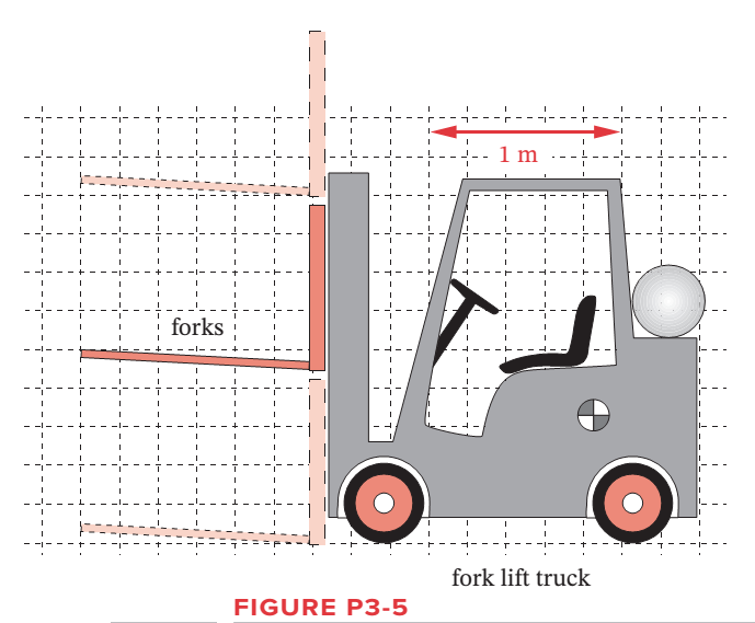
Design a pin-jointed linkage that will guide the forks of the fork lift truck in Figure P3-5 up and down in an approximate straight line over the range of motion shown. Arrange the fixed pivots so they are close to some part of the existing frame or body of the truck.
Expert Solution & Answer
Want to see the full answer?
Check out a sample textbook solution
Students have asked these similar questions
Problem 4-6a
The link lengths (a, b, c, d) and the value of 62 for a crank-rocker linkage are defined as
2, 7, 9, 6, 30°, respectively. Draw the scaled linkage. Find all possible solutions (both
open and crossed) for angles 03 and 04 graphically.
Open
B
3
A
LNCS
4
04
GCS
O4
Crossed
(This is not the scaled kinematic diagram.)
Problem 4-7a
Repeat Problem 4-6a except solve by the vector loop method.
Show how you would find the velocity of each point (no values given just the equation) for an overlapping/superimpose 4 bar linkage. Find the equation for 100 degree.
Problem 4-6a
The link lengths (a, b, c, d) and the value of 2 for a crank-rocker linkage are defined as
2, 7, 9, 6, 30°, respectively. Draw the scaled linkage. Find all possible solutions (both
open and crossed) for angles 03 and 04 graphically.
Орen
B
A
LNCS
4
a
GCS
र 4
4"
Crossed
(This is not the scaled kinematic diagram.)
Problem 4-7a
Repeat Problem 4-6a except solve by the vector loop method.
Chapter 3 Solutions
DESIGN OF MACHINERY
Ch. 3 - Define the following examples as path, motion, or...Ch. 3 - Design a fourbar Grashof crank-rocker for 90 of...Ch. 3 - Prob. 3.3PCh. 3 - Design a fourbar mechanism to give the two...Ch. 3 - Prob. 3.5PCh. 3 - Prob. 3.6PCh. 3 - Repeat Problem 3-2 with a quick-return time ratio...Ch. 3 - Design a sixbar drag link quick-return linkage for...Ch. 3 - Design a crank-shaper quick-return mechanism for a...Ch. 3 - Find the two cognates of the linkage in Figure...
Ch. 3 - Find the three equivalent geared fivebar linkages...Ch. 3 - Design a sixbar single-dwell linkage for a dwell...Ch. 3 - Design a sixbar double-dwell linkage for a dwell...Ch. 3 - Figure P3-3 shows a treadle-operated grinding...Ch. 3 - Figure P3-4 shows a non-Grashof fourbar linkage...Ch. 3 - Prob. 3.16PCh. 3 - Prob. 3.17PCh. 3 - Prob. 3.18PCh. 3 - Design a pin-jointed linkage that will guide the...Ch. 3 - Figure P3-6 shows a V-link off-loading mechanism...Ch. 3 - Prob. 3.21PCh. 3 - Prob. 3.22PCh. 3 - Figure P3-8 shows a fourbar linkage used in a...Ch. 3 - Prob. 3.24PCh. 3 - Prob. 3.25PCh. 3 - Prob. 3.26PCh. 3 - Prob. 3.27PCh. 3 - Prob. 3.28PCh. 3 - Prob. 3.29PCh. 3 - Prob. 3.30PCh. 3 - Design a Hoeken straight-line linkage to give...Ch. 3 - Design a Hoeken straight-line linkage to give...Ch. 3 - Prob. 3.33PCh. 3 - Prob. 3.34PCh. 3 - Prob. 3.35PCh. 3 - Find the Grashof condition, inversion, any limit...Ch. 3 - Prob. 3.37PCh. 3 - Prob. 3.38PCh. 3 - Prob. 3.39PCh. 3 - Draw the Roberts diagram and find the cognates of...Ch. 3 - Prob. 3.41PCh. 3 - Find the Grashof condition, any limit positions,...Ch. 3 - Prob. 3.43PCh. 3 - Prob. 3.44PCh. 3 - Prob. 3.45PCh. 3 - Prob. 3.46PCh. 3 - Prob. 3.47PCh. 3 - Prob. 3.48PCh. 3 - Prob. 3.49PCh. 3 - Prob. 3.50PCh. 3 - Prob. 3.51PCh. 3 - Prob. 3.52PCh. 3 - Prob. 3.53PCh. 3 - Prob. 3.54PCh. 3 - Prob. 3.55PCh. 3 - Prob. 3.56PCh. 3 - Prob. 3.57PCh. 3 - Prob. 3.58PCh. 3 - Prob. 3.59PCh. 3 - Prob. 3.60PCh. 3 - Prob. 3.61PCh. 3 - Prob. 3.62PCh. 3 - Prob. 3.63PCh. 3 - Prob. 3.64PCh. 3 - Prob. 3.65PCh. 3 - Prob. 3.66PCh. 3 - Design a fourbar Grashof crank-rocker for 120 of...Ch. 3 - Prob. 3.68PCh. 3 - Design a fourbar Grashof crank-rocker for 80 of...Ch. 3 - Design a sixbar drag link quick-return linkage for...Ch. 3 - Design a crank shaper quick-return mechanism for a...Ch. 3 - Design a sixbar, single-dwell linkage for a dwell...Ch. 3 - Design a sixbar, single-dwell linkage for a dwell...Ch. 3 - Prob. 3.74PCh. 3 - Using the method of Example 3-11, show that the...Ch. 3 - Prob. 3.76PCh. 3 - Prob. 3.77PCh. 3 - Prob. 3.78PCh. 3 - The first set of 10 coupler curves on page 1 of...Ch. 3 - Prob. 3.80PCh. 3 - Prob. 3.81PCh. 3 - Prob. 3.82PCh. 3 - Prob. 3.83PCh. 3 - Prob. 3.84PCh. 3 - Prob. 3.85PCh. 3 - Prob. 3.86PCh. 3 - Prob. 3.87PCh. 3 - The side view of the upper section of a...Ch. 3 - Design a fourbar mechanism to give the three...Ch. 3 - Design a fourbar mechanism to give the three...Ch. 3 - Design a fourbar Grashof crank-rocker for 60...Ch. 3 - Design a crank-shaper quick-return mechanism for a...Ch. 3 - Figure P3-22 shows a non-Grashof fourbar linkage...Ch. 3 - Prob. 3.94PCh. 3 - Design a fourbar Grashof crank-rocker for 80...Ch. 3 - Design a sixbar drag link quick-return linkage for...
Knowledge Booster


Learn more about
Need a deep-dive on the concept behind this application? Look no further. Learn more about this topic, mechanical-engineering and related others by exploring similar questions and additional content below.Similar questions
- Figure below shows a four-bar linkage (non-scaled diagram) at an instant. The input angle is equal to the output angle (02 - 04) and the transmission angle is 30°. The input link is extended beyond joint B and an input force (Fin) is applied at the end of it, while an output force is drawn from the midpoint of the output link. If an output force of 30 N is desired from an input force of 10 N, how far the input link should be extended, i.e., what is the distance from point B to the point where Fin is applied. Fin B out undefined 02 04 A. Non-scaled diagram; AB = 10, CD=r4 = 30 (output), all in mmarrow_forwardOestion-1: An elliptical trammel is a double slider-crank mechanism used for drawing ellipses as shown in figure (a) below. Position vectors for various linkages are drawn as shown in figure (b). Where: R2: represents position vector for a Slider which can slide along x-axis only R4: represents position vector for a Slider which can slide along y-axis only R3 represents position vector for a crank (Take R3 = 10mm, 03 = 45°, V3 = 10mm/sec) Rix: This is aligned with x-axis and represents fixed position of slider (R4) from ground RIY: This is aligned with Y-axis and represents fixed position of slider (R2) from ground Take: R13= 20mm, Rịy=40mm. Assume crank is rotating with constant velocity Note: all angles are measured counterclockwise from x-axis. a) Formulate the vector loop, position, velocity and acceleration equations b) Simplify the equations by plugging in respective angles and solve to find R2, R4, linear velocities of both sliders and angular acceleration of crank. c) Identify…arrow_forwardFigure Q2-2 shows a schematic of a retractable landing gear of aircraft. The retraction mechanism is a 4 bar linkage (O1ABO2), which is actuated by a hydraulic cylinder and piston, D, pivoted at E with a joint at C to link O,A. Hydraulic cylinder & piston D Joint for landing gear wheel Figure Q2-2 Use the Gruebler's equation of DoF (Degrees of Freedom) of a linkage mechanism to assess if the landing gear produces the required retraction motion. 0,02 may be considered as the ground link. i) Hint: The joint of the wheel is not part of the linkage mechanism. The number of DoF may be used to check if it is a linkage with certain motions or a fixed structure. ii) The dimensions of the 4 bar linkage (O1ABO2) are measured as O102 = 800 mm, O1A = 780 mm, AB = 200 mm and O2B = 400 mm. Use Grashof condition to determine the specific type of this linkage. You may find the Gruebler's equation useful: M = 3(L – 1) – 2J where, M is degree of freedom (DoF) L is number of links J is number of jointsarrow_forward
- Refer to the figure. The 4-wayvalve has a blocked center spool and threepositions. Solenoid B is energized pushingthe spool to the left.What direction will the cylinders move:extend (to the right) or retract (to the left)?Which cylinder moves first during this stepand why?arrow_forwardPls help me with my plates Block 4 slides in the slot in the fixed piece 1. Axis Q2 of crank 2 is fixed on 1. Q2A = 1.5 inches, and AB = 4.5 inches. Draw the mechanism, assuming dimensions for 1, if desired or use center lines only. Draw the four-bar linkage for this mechanism, properly rotate the linkage Q2ABQ4∞, name each link, and show the finite infinite cranks.arrow_forwarda. Sketch the kinematic diagram of the following mechanism shown and give brief description on how each link move relative to each other. Compute the degree of freedom.b. Determine the location of all revolute pairs shown in the figure as the tip of the loadermoves from L to L’.arrow_forward
- A general fourbar linkage configuration and its notation are shown in Figure below. The link lengths, coupler point location, and the values of 02 and w2 for the same fourbar linkages as used for position analysis in Chapter 4 are redefined in Table below. For the row c, draw the linkage to scale and Using an analytical method calculate w3 and w4 and find the velocity of point P. find the velocities of the pin joints A and. RPA Y B 4 03 04 02 1 02 FIGURE P6-1 Configuration and terminology for the pin-jointed fourbar linkage of Problems 6-4 to 6-5 TABLE P6-1 Data for Problems 6-4 to 6-5† Row Link 1 Link 2 Link 3 Link 4 02 Rpa 83 02 a 2 7 9. 30 10 30 7 9. 8 85 -12 9 25 3 10 8 45 -15 10 80arrow_forwardA general fourbar linkage configuration and its notation are shown in Figure below. The link lengths, coupler point location, and the values of 02 and w2 for the same fourbar linkages as used for position analysis in Chapter 4 are redefined in Table below. For the row c, draw the linkage to scale and Using an analytical method calculate w3 and w4 and find the velocity of point P. find the velocities of the pin joints A and. RPA AY 2 04 02 04 FIGURE P6-1 Configuration and terminology for the pin-Jointed fourbar linkage of Problems 6-4 to 6-5 TABLE P6-1 Data for Problems 6-4 to 6-5† Row Link 1 Link 2 Link 3 Link 4 02 02 Rpa 83 6. 2 7 30 10 6. 30 b. 9 3 8 85 -12 9. 25 10 6. 8 45 -15 10 80 O73arrow_forwardThe number of degrees of freedom of the linkage shown in the figure.arrow_forward
- Problem 2 The linkage in Figure P7-5b has O,A = O2A = 0.75, AB= 1.5, and AC = 1.2 in. The effective crank angle in the position shown is 77° and angle BAC = 30°. Find a3, A4, AB,Ac for the position shown for @2 = 15 rad/sec and a2 = 10 rad/sec in the directions shown using an analytical method. (Hint: Create an effective linkage for the position shown and analyze it as a pin-jointed fourbar.)the linkage has a parallelogram form Assume rolling contact C @2 A 3 В a2 2 4 04arrow_forwardQ3) For the mechanism shown in the figure: 1. Determine the numbers of links, joints, and instantaneous centers 2. List all the instantaneous centers 3. Locate all the instantaneous centers and mark them by Aronhold Kennedy's theorem 4. Draw the diagram and mark all details along with marking the fixed and permanent centers only ye B. 11. miniszhaarrow_forwardFor the four-bar- linkage shown in the following figure. BC=68mm, CD=100mm, AD=120mm. Determine the range of AB to make it a crank-rocker mechanism.arrow_forward
arrow_back_ios
SEE MORE QUESTIONS
arrow_forward_ios
Recommended textbooks for you
 Elements Of ElectromagneticsMechanical EngineeringISBN:9780190698614Author:Sadiku, Matthew N. O.Publisher:Oxford University Press
 Mechanics of Materials (10th Edition)Mechanical EngineeringISBN:9780134319650Author:Russell C. HibbelerPublisher:PEARSON
 Thermodynamics: An Engineering ApproachMechanical EngineeringISBN:9781259822674Author:Yunus A. Cengel Dr., Michael A. BolesPublisher:McGraw-Hill Education
 Control Systems EngineeringMechanical EngineeringISBN:9781118170519Author:Norman S. NisePublisher:WILEY
 Mechanics of Materials (MindTap Course List)Mechanical EngineeringISBN:9781337093347Author:Barry J. Goodno, James M. GerePublisher:Cengage Learning
 Engineering Mechanics: StaticsMechanical EngineeringISBN:9781118807330Author:James L. Meriam, L. G. Kraige, J. N. BoltonPublisher:WILEY
Elements Of Electromagnetics
Mechanical Engineering
ISBN:9780190698614
Author:Sadiku, Matthew N. O.
Publisher:Oxford University Press
Mechanics of Materials (10th Edition)
Mechanical Engineering
ISBN:9780134319650
Author:Russell C. Hibbeler
Publisher:PEARSON
Thermodynamics: An Engineering Approach
Mechanical Engineering
ISBN:9781259822674
Author:Yunus A. Cengel Dr., Michael A. Boles
Publisher:McGraw-Hill Education
Control Systems Engineering
Mechanical Engineering
ISBN:9781118170519
Author:Norman S. Nise
Publisher:WILEY
Mechanics of Materials (MindTap Course List)
Mechanical Engineering
ISBN:9781337093347
Author:Barry J. Goodno, James M. Gere
Publisher:Cengage Learning
Engineering Mechanics: Statics
Mechanical Engineering
ISBN:9781118807330
Author:James L. Meriam, L. G. Kraige, J. N. Bolton
Publisher:WILEY
Differences between Temporary Joining and Permanent Joining.; Author: Academic Gain Tutorials;https://www.youtube.com/watch?v=PTr8QZhgXyg;License: Standard Youtube License