
Concept explainers
Videos
A
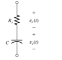
Figure P3.39
Want to see the full answer?
Check out a sample textbook solution
Chapter 3 Solutions
Electrical Engineering: Principles & Applications (7th Edition)


- Calculate capacitance Cand voltage U over resistance. What is the peak value of resistance's voltage? Voltage source e(t) = ésin(wt + 45°). Resistance R-50, circuit's total reactance X-50, inductance L =50mH, ê -40V and frequency f =50Hz. R L Give the answers to one decimal place. Do not write numbers in the complex number form! Absolute value of voltage source (RMS value): V Total impedance of circuit (absolute value): Capacitance: μF Absolute value of current (RMS value) supplied by voltage source: Phase angle of current: degrees Peak value of resistances voltage: 22 Aarrow_forwardA. Find the equivalent capacitance of the combination shown in the figure. (C2 = 2µF, C3 = 3µF) B. Determine the charge on each capacitor, if there is a potential difference of 900V C. Determine the voltages across each capacitorarrow_forward4. For the circuit shown in Figure...., determine (a) the total circuit capacitance, (b) the total energy in the circuit, and (c) the charges in the capacitors shown as C₁ and C₂. 2 F 2μF HH 2μF 2μF 2μF 2 μF C₁ HH HI 2 μF 50 V H 2μF C₂arrow_forward
- 3-10 A0.25-F capacitor has a current waveform i(t) as shown in Figure P3–10. Determine and plot the voltage waveform v(t) as a function of time. The capacitor is initially a and plot the voltage waveform v(t) as a function of time. The capacitor is imu uncharged. FIGURE P3-10 ilt) 4 A 6. -4 Aarrow_forwarda) The voltage across a 20uF capacitance is v. = 50 sin( at - 80) volts and Frequency equal to 100 Hz. Determine the current through the capacitor i and sketch its waveform. b) Define phasorarrow_forward1. What impedance vector 0 – j22 represents:A. A pure resistance.B. A pure inductance.C. A pure capacitance.D. An inductance combined with a resistance.arrow_forward
- Time left 0 A resistor of 42 ohm is connected in series with a capacitor of 50 micro farad. if a supply of 240 V, 60 Hz is connected across the arrangement then the current flowing in the capacitor is. O a. 3.14 A O b. 35.4 A O c. 31.4 A O d. 3.54 Aarrow_forward(i) Determine the unknown true power, P2 and reactive power Q3. (ii) Draw the power triangle and determine total apparent power. (iii) Identify whether the unknown reactive component at the Load 3 is an inductor or capacitor.arrow_forwardFor the network shown in Figure (Q5), Find: 1. The total equivalent inductance (Lequiv.). 2. If the current waveform shown in Figure (6) is applied to the (Leguiv). Determine an expression for the voltage across it. 6H 10 H 9H 4H SH 3 H 20 H 13H Lequiv. Figure (Q5) i (A) - (ms) 10 12 -5- Figure (6)arrow_forward
- Acertain electric circuit has a resistor and a capacitor. The capacitor is initially charged to 100 V. When the power supply is detached, the capacitor voltage decays with time, as the following data table shows. Find a functional description of the capacitor voltage v as a function of time t. Plot the function and the data on the same plot.arrow_forward6) When the frequency of an a.c. circuit containing resistance and capacitance is decreased, the current (a) decreases (b) increases (c) stays the same 7) In a series a.c. circuit the voltage across a pure inductance is 12 V and the voltage across a pure resistance is 5 V. The supply voltage is (a) 13 V (b) 17 V (c) 7 V (d) 2.4 V 8) The impedance of a coil, which has a resistance of X ohms and an inductance of Y henrys, connected across a supply of frequency K Hz, is (a) 2π Κ Υ (b) X + Y (c) √x² + y² (d) X² + (2nKY)²arrow_forward6) When the frequency of an a.c. circuit containing resistance and capacitance is decreased, the current (a) decreases (b) increases (c) stays the same 7) In a series a.c. circuit the voltage across a pure inductance is 12 V and the voltage across a pure resistance is 5 V. The supply voltage is (a) 13 V (b) 17 V (c) 7 V (d) 2.4 V 8) The impedance of a coil, which has a resistance of X ohms and an inductance of Y henrys, connected across a supply of frequency K Hz, is (a) 2π Κ Υ (b) X + Y (c) √x² + y² (d) √X² + (2nKY)² 9) When a capacitor is connected to an a.c. supply the current (a) leads the voltage by 180° (c) leads the voltage by 1/2 rad (b) is in phase with the voltage (d) lags the voltage by 90° 10) In an R-L-C series a.c. circuit a current of 5 A flows when the supply voltage is 100 V. The phase angle between current and voltage is 60° lagging. Which of the following statements is false? (a) The circuit is effectively inductive (c) The equivalent circuit reactance is 25 2 (b)…arrow_forward
 Introductory Circuit Analysis (13th Edition)Electrical EngineeringISBN:9780133923605Author:Robert L. BoylestadPublisher:PEARSON
 Delmar's Standard Textbook Of ElectricityElectrical EngineeringISBN:9781337900348Author:Stephen L. HermanPublisher:Cengage Learning
 Programmable Logic ControllersElectrical EngineeringISBN:9780073373843Author:Frank D. PetruzellaPublisher:McGraw-Hill Education
 Fundamentals of Electric CircuitsElectrical EngineeringISBN:9780078028229Author:Charles K Alexander, Matthew SadikuPublisher:McGraw-Hill Education
 Electric Circuits. (11th Edition)Electrical EngineeringISBN:9780134746968Author:James W. Nilsson, Susan RiedelPublisher:PEARSON
 Engineering ElectromagneticsElectrical EngineeringISBN:9780078028151Author:Hayt, William H. (william Hart), Jr, BUCK, John A.Publisher:Mcgraw-hill Education,