
Electrical Engineering: Principles & Applications (7th Edition)
7th Edition
ISBN: 9780134484143
Author: Allan R. Hambley
Publisher: PEARSON
expand_more
expand_more
format_list_bulleted
Concept explainers
Videos
Textbook Question
Chapter 3, Problem 3.71P
Consider the circuit shown in Figure P3.71 in which
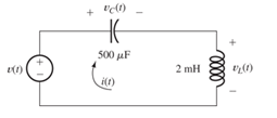
Figure P3.71
Expert Solution & Answer
Want to see the full answer?
Check out a sample textbook solution
Students have asked these similar questions
A capacitor "C", an inductor "L" and a switch "S" are connected in series. When the switch is open, the plate to the left of the capacitor has charge "Qo". The switch is closed the load and current vary sinusoidally with time. Represent graphically the load "Qo" and the intensity of current "I" as a function of time "t", and explain why the current leads the load by a phase difference of 90°.
3-10 A0.25-F capacitor has a current waveform i(t) as shown in Figure P3–10. Determine
and plot the voltage waveform v(t) as a function of time. The capacitor is initially
a
and plot the voltage waveform v(t) as a function of time. The capacitor is imu
uncharged.
FIGURE P3-10
ilt)
4 A
6.
-4 A
What impedance vector (0- j15) Ohms represents:A. A pure resistance. C. A pure capacitance.B. A pure inductance. D. An inductance combined with a capacitance.
Chapter 3 Solutions
Electrical Engineering: Principles & Applications (7th Edition)
Ch. 3 - What is a dielectric material? Give two examples.Ch. 3 - Briefly discuss how current can flow “through” a...Ch. 3 - What current flows through an ideal capacitor if...Ch. 3 - Describe the internal construction of capacitors.Ch. 3 - A voltage of 50 V appears across a 10F capacitor....Ch. 3 - A 2000F capacitor, initially charged to 100V, is...Ch. 3 - A 5F Capacitor ischarged to 1000 V. Determine the...Ch. 3 - The voltage across a 10F capacitor is given by v...Ch. 3 - The voltage across a 1F capacitor is given by...Ch. 3 - Prior to t = 0, a 100F capacitance is uncharged...
Ch. 3 - The current through a 0.5F capacitor is shown in...Ch. 3 - Determine the capacitor voltage, power, and stored...Ch. 3 - A current given by i(t)=Imcos(t) flows through a...Ch. 3 - The current through a 3F capacitor is shown in...Ch. 3 - A constant (dc) current i(t)=3 mA flows into a 50F...Ch. 3 - The energy stored in a 2F capacitor is 200 J and...Ch. 3 - At t=t0 the voltage across a certain capacitance...Ch. 3 - An unusual capacitor has a capacitance that is a...Ch. 3 - For a resistor, what resistance corresponds to a...Ch. 3 - Suppose we have a very large capacitance (ideally,...Ch. 3 - We want to store sufficient energy in a 001-F...Ch. 3 - A 100F capacitor has a voltage given by v(t)=1010...Ch. 3 - How are capacitances combined in series and in...Ch. 3 - Find the equivalent capacitance for each of the...Ch. 3 - Find the equivalent capacitance between terminals...Ch. 3 - A network has a 5F capacitance in series with the...Ch. 3 - What are the minimum and maximum values of...Ch. 3 - Two initially uncharged capacitors C1=15F and...Ch. 3 - Suppose that we are designing a cardiac pacemaker...Ch. 3 - Suppose that we have two 100F capacitors One is...Ch. 3 - Determine the capacitance of a parallel-plate...Ch. 3 - A 100-pF capacitor is constructed of parallel...Ch. 3 - We have a parallel-plate capacitor with plates of...Ch. 3 - Suppose that we have a 1000-pF parallel-plate...Ch. 3 - Two 1F capacitors have an initial voltage of 100 V...Ch. 3 - Prob. 3.36PCh. 3 - Prob. 3.37PCh. 3 - A parallel-plate capacitor is used as a vibration...Ch. 3 - A 0.1F capacitor has a parasitic series resistance...Ch. 3 - Prob. 3.40PCh. 3 - Briefly discuss how inductors are constructed.Ch. 3 - The current flowing through an inductor is...Ch. 3 - If the current through an ideal inductor is...Ch. 3 - Briefly discuss the fluid-flow analogy for an...Ch. 3 - The current flowing through a 2-H inductance is...Ch. 3 - The current flowing through a 100-mH inductance is...Ch. 3 - The current flowing through a 2-H inductance is...Ch. 3 - The voltage across a 2-H inductance is shown in...Ch. 3 - The voltage across a 10 H inductance is given by...Ch. 3 - A 2-H inductance has i(0) = 0 and v(t)=texp(t) for...Ch. 3 - A constant voltage of 10V is applied to a 50H...Ch. 3 - At t = 0, the current flowing in a 05-H inductance...Ch. 3 - The current through a 100-mH inductance is given...Ch. 3 - Prior to t= 0, the current in a 2-H inductance is...Ch. 3 - At t= 0, a constant 5-V voltage source is applied...Ch. 3 - Prob. 3.56PCh. 3 - Al t= 5 s, the energy stored in a 2-H inductor is...Ch. 3 - What value of inductance (having zero initial...Ch. 3 - To what circuit element does a very large...Ch. 3 - The voltage across an inductance L is given by...Ch. 3 - Discuss how inductances are combined in series and...Ch. 3 - Determine the equivalent inductance for each of...Ch. 3 - Find the equivalent inductance for each of the...Ch. 3 - What is the maximum inductance that can be...Ch. 3 - Suppose we want to combine (in series or in...Ch. 3 - Prob. 3.66PCh. 3 - Two inductances L1=1H and L2=2H are connected in...Ch. 3 - A 10-mH inductor has a parasitic series resistance...Ch. 3 - Draw the equivalent circuit for a real inductor,...Ch. 3 - Suppose that the equivalent circuit shown in...Ch. 3 - Consider the circuit shown in Figure P3.71 in...Ch. 3 - The circuit shown in Figure P3.72 has...Ch. 3 - Describe briefly the physical basis for mutual...Ch. 3 - The mutually coupled inductances in Figure P3.74...Ch. 3 - Repeat Problem P3.74 with the dot placed at the...Ch. 3 - a. Derive an expression for the equivalent...Ch. 3 - Consider the parallel inductors shown in Figure...Ch. 3 - Consider the mutually coupled inductors shown in...Ch. 3 - Mutually coupled inductances have...Ch. 3 - The current through a 200-mH inductance is given...Ch. 3 - A 1-H inductance has iL(0)=0 and vL(t)=texp(t) for...Ch. 3 - The current flowing through a 10F capacitor having...Ch. 3 - Determine the equivalent capacitance Ceq for...Ch. 3 - A certain parallel-plate capacitor has plate...Ch. 3 - A 2-mH inductance has iab=0.3sin(2000t)A . Find an...Ch. 3 - Determine the equivalent inductance Leq between...Ch. 3 - Given that vc(t)=10sin(1000t)V , find vs(t)in the...Ch. 3 - Prob. 3.7PTCh. 3 - The current flowing through a 20F capacitor having...
Knowledge Booster


Learn more about
Need a deep-dive on the concept behind this application? Look no further. Learn more about this topic, electrical-engineering and related others by exploring similar questions and additional content below.Similar questions
- a) The voltage across a 20uF capacitance is v. = 50 sin( at - 80) volts and Frequency equal to 100 Hz. Determine the current through the capacitor i and sketch its waveform. b) Define phasorarrow_forwardhow do i calculate the inverse capacitance and its uncertainty if the capacitance value 1.8748+/- 0.0006. please show steps im using this example to do my other values.arrow_forwardAt 0-, no currrent flows through the capacitors because they are open, how did you combine the capacitors for the voltage divider since it is the capacitance value and not reactance, is it right? Can we just combine the capacitance value? Please explain. I did not understand..arrow_forward
- Let's say you measure t1/2 to be 0.037 seconds and the resistance in the circuit is 68 Ohms. Then what is the capacitance in micro Farads? Answer in micro Farads.arrow_forwardAn electrical circuit with a sinusoidal voltage source, a resistor, and a capacitor all connected in series. The voltage across the capacitor: Select one: a. Leads the current in the capacitor by exactly 90o b. Is in phase with the sinusoidal voltage source c. Is in phase with the voltage across the resistor d. Leads the current in the circuit by 90o e. Lags the current in the circuit by 90oarrow_forwardFind the equivalent inductance as seen from the terminals shown in the figure.arrow_forward
- Support that there. Icincuit Esithu an reasistanee on the and capacitance of /4 F. The EMF is ) 4 Cos 2t , The initial is an RC Cnerat current. The alternating cincuit is '/ 2 L Elt) the cincuit is qu(0) = 1V. Find the charge on the cincuit after t seconds. charge onarrow_forwardFind the capacitance if correct will upvote otherwise i will dislike...arrow_forwardCalculate the steady state currents flowing through inductors L₁ and L₂ and the steady state voltage across capacitor C in the circuit L₁ mm Vs = 20 V L₁ = 4 mH R₁ = 1 A R₂ = 3 L₂= 7 mH C = 6 4F shown below: Ri wwwww HH Carrow_forward
- the parallel connection of a resistor and a capacitor takes 0.6 A rms from a 120 V rms voltage source. Given the 0.7 leading power factor, find the resistance and capacitance at 400Hz.arrow_forwardTime left 0 A resistor of 42 ohm is connected in series with a capacitor of 50 micro farad. if a supply of 240 V, 60 Hz is connected across the arrangement then the current flowing in the capacitor is. O a. 3.14 A O b. 35.4 A O c. 31.4 A O d. 3.54 Aarrow_forward5: An inductor is one of important device in electrical circuits. To study response of it in pure form,inductor 240 mH is connected to AC source of maximum voltage 280 V, with a frequency of 120 Hz.Predict the rms current passing through the circuit. Can you predict the change in rms current if thefrequency is increased to 5 kHz? Are there any similar properties for a transformer compared withinductor? Is it possible to operate inductor with DC source? Justify your answer.arrow_forward
arrow_back_ios
SEE MORE QUESTIONS
arrow_forward_ios
Recommended textbooks for you
 Introductory Circuit Analysis (13th Edition)Electrical EngineeringISBN:9780133923605Author:Robert L. BoylestadPublisher:PEARSON
 Delmar's Standard Textbook Of ElectricityElectrical EngineeringISBN:9781337900348Author:Stephen L. HermanPublisher:Cengage Learning
 Programmable Logic ControllersElectrical EngineeringISBN:9780073373843Author:Frank D. PetruzellaPublisher:McGraw-Hill Education
 Fundamentals of Electric CircuitsElectrical EngineeringISBN:9780078028229Author:Charles K Alexander, Matthew SadikuPublisher:McGraw-Hill Education
 Electric Circuits. (11th Edition)Electrical EngineeringISBN:9780134746968Author:James W. Nilsson, Susan RiedelPublisher:PEARSON
 Engineering ElectromagneticsElectrical EngineeringISBN:9780078028151Author:Hayt, William H. (william Hart), Jr, BUCK, John A.Publisher:Mcgraw-hill Education,
Introductory Circuit Analysis (13th Edition)
Electrical Engineering
ISBN:9780133923605
Author:Robert L. Boylestad
Publisher:PEARSON
Delmar's Standard Textbook Of Electricity
Electrical Engineering
ISBN:9781337900348
Author:Stephen L. Herman
Publisher:Cengage Learning
Programmable Logic Controllers
Electrical Engineering
ISBN:9780073373843
Author:Frank D. Petruzella
Publisher:McGraw-Hill Education
Fundamentals of Electric Circuits
Electrical Engineering
ISBN:9780078028229
Author:Charles K Alexander, Matthew Sadiku
Publisher:McGraw-Hill Education
Electric Circuits. (11th Edition)
Electrical Engineering
ISBN:9780134746968
Author:James W. Nilsson, Susan Riedel
Publisher:PEARSON
Engineering Electromagnetics
Electrical Engineering
ISBN:9780078028151
Author:Hayt, William H. (william Hart), Jr, BUCK, John A.
Publisher:Mcgraw-hill Education,
Lecture - 10 Transmission Line Parameters; Author: nptelhrd;https://www.youtube.com/watch?v=lr1jgbR5ca8;License: Standard YouTube License, CC-BY
Inductance of Three Phase Transmission lines (Symmetrical and Unsymmetrical Configurations); Author: Ravindra Prasad Pendyala;https://www.youtube.com/watch?v=CbFBxjfHYFY;License: Standard Youtube License