
System Dynamics
3rd Edition
ISBN: 9780073398068
Author: III William J. Palm
Publisher: MCG
expand_more
expand_more
format_list_bulleted
Concept explainers
Videos
Textbook Question
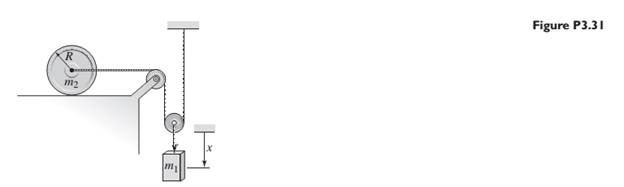
Chapter 3, Problem 3.31P
Assume the cylinder in Figure P3.31 rolls without slipping. Neglect the mass of the pulleys and derive the equation of motion of the system in terms of the displacement x.
Expert Solution & Answer
Want to see the full answer?
Check out a sample textbook solution
Students have asked these similar questions
b) The mass of gear A in Figure Q4(b) is 20 kg, its radius is 240 mm and its
radius of gyration is 150 mm. The mass of gear B is 10 kg, its radius is 180
mm and its radius of gyration is 100 mm. Calculate the angular acceleration of
gear B when a torque M = 12 Nm is applied to the shaft of gear A, neglect
friction.
"A = 240 mm
rB - 180 mm
An electric motor is accelerating a 250 kg load with acceleration of 1.2 m/s? througha gear box as shown Figure Q1(b). The rope that carries the load and spiral spring are encircled on a pulley with diameter 1.2m. Gear box ratio is 0. 1 and gear box efficiency is 100%, while gear box equivalent moment inertia is 5.55 km?. Neglect friction effect in this drive system and assume spiral spring force is X newtonCalculate the torque of the motor needed to bring up the load with acceleration1.2 m/s?.
For each of the systems shown in Figure P4.52, the input is the force f andthe outputs are the displacements x1 and x2 of the masses. The equilibriumpositions with f = 0 correspond to x1 = x2 = 0. Neglect any friction betweenthe masses and the surface. Derive the equations of motion of the systems.
Chapter 3 Solutions
System Dynamics
Ch. 3 - Prob. 3.1PCh. 3 - A baseball is thrown horizontally from the...Ch. 3 - For the mass shown in Figure 3.1.3b. m=10 kg, =25...Ch. 3 - A particle of mass m=19 kg slides down a...Ch. 3 - A particle of mass m slides down a frictionless...Ch. 3 - A radar tracks the flight of a projectile (see...Ch. 3 - Table 3.2.1 gives the inertia IO for a point mass...Ch. 3 - A motor supplies a moment M to the pulley of...Ch. 3 - Figure P3.9 shows an inverted pendulum. Obtain the...Ch. 3 - The two masses shown in Figure P3.10 are released...
Ch. 3 - The motor in Figure P3.11 lifts the mass mL by...Ch. 3 - Instead of using the system shown in Figure 3.2.6a...Ch. 3 - Consider the cart shown in Figure P3.13. Suppose...Ch. 3 - Consider the cart shown in Figure P3.13. Suppose...Ch. 3 - Consider the spur gears shown in Figure P3.15,...Ch. 3 - Consider the spur gears shown in Figure P3.15,...Ch. 3 - Derive the expression for the equivalent inertia...Ch. 3 - Prob. 3.18PCh. 3 - The geared system shown in Figure P3.19 represents...Ch. 3 - Prob. 3.20PCh. 3 - Prob. 3.21PCh. 3 - Prob. 3.22PCh. 3 - For the geared system shown in Figure P3.23,...Ch. 3 - For the geared system discussed in Problem 3.23,...Ch. 3 - The geared system shown in Figure P3.25 is similar...Ch. 3 - Consider the rack-and-pinion gear shown in Figure...Ch. 3 - The lead screw (also called a power screw or a...Ch. 3 - Prob. 3.29PCh. 3 - Derive the equation of motion of the block of mass...Ch. 3 - Assume the cylinder in Figure P3.31 rolls without...Ch. 3 - Prob. 3.33PCh. 3 - Prob. 3.34PCh. 3 - A slender rod 1.4 m long and of mass 20 kg is...Ch. 3 - Prob. 3.36PCh. 3 - Prob. 3.37PCh. 3 - The pendulum shown in Figure P3.38 consists of a...Ch. 3 - Prob. 3.39PCh. 3 - A single link of a robot arm is shown in Figure...Ch. 3 - 3.41 It is required to determine the maximum...Ch. 3 - Figure P3.42 illustrates a pendulum with a base...Ch. 3 - Figure P3.43 illustrates a pendulum with a base...Ch. 3 - 3.44 The overhead trolley shown in Figure P3.44 is...Ch. 3 - Prob. 3.45PCh. 3 - The “sky crane” shown on the text cover was a...
Knowledge Booster


Learn more about
Need a deep-dive on the concept behind this application? Look no further. Learn more about this topic, mechanical-engineering and related others by exploring similar questions and additional content below.Similar questions
- For this problem, take a look at Figure 2 below. A disk with uniformly distributed mass m, radius R, and center of mass at point O is connected to a combination of springs at point P, which are then connected to a fixed wall. The disk rolls without slipping at point Q along an inclined plane that is at an angle a from the horizontal. Gravity acts in the vertical direction (towards the bottom of the page). ₁ is the linear coordinate of the point O along the inclined plane. The positive direction of ₁ is as shown. When the springs are undeflected, *₁ = 0. An angle , about the instant center of rotation, is shown. You may assume that the motion (and therefore angle ) is small. puny m Massless structure between springs R Figure 2: System schematic. Your tasks: A Draw the FBD for the disk. Don't forget the forces at point Q B Derive the equation of motion with as the dynamic variable. Be sure to put it in input-output standard form (inputs and constant forces on the right, things related to…arrow_forwardUse the energy method to deriving the equations of motion for systems in Fig. 3, 4. Then calculate the resulting displacements due to the application of 1 N force.arrow_forwardQ5 A sphere with mass m and radius r is released with no initial velocity, and it rolls without slipping on the incline as shown in Figure Q5. The angle 9 is 30°. The mass moment of inertia for a sphere is (2/5) m r2. Go Figure Q5 (a) In this case, what is the relationship between linear and angular accelerations? Explain. (b) Draw the free-body diagram and the kinetic diagram for the sphere. (c) Calculate the minimum friction coefficient required between sphere and incline. (d) What is the mass moment of inertia and what is its role in second Newton's law, compared to the role of massarrow_forward
- The rope shown in the figure below is wound around a cylinder of mass 4.0 kg and I = 0.020 kg m2, about the cylinder axis. If the cylinder rolls without slipping, what is the linear acceleration of its center of mass? What is the frictional force? Use an axis along the cylinder axis for your computation. What happens if the frictional force between table and cylinder is negligible? Choose any axis for your computation.arrow_forwardCam mechanisms are used in many machines. For example, cams open and close the valves in your car engine to admit gasoline vapor to each cylinder and to allow the escape of exhaust. The principle is illustrated in the figure below, showing a follower rod (also called a pushrod) of mass m resting on a wedge of mass M. The sliding wedge duplicates the function of a rotating eccentric disk on a camshaft in your car. Assume that there is no friction between the wedge and the base, between the pushrod and the wedge, or between the rod and the guide through which it slides. When the wedge is pushed to the left by the force F, the rod moves upward and does something such as opening a valve. By varying the shape of the wedge, the motion of the follower rod could be made quite complex, but assume that the wedge makes a constant angle of 0 = 19.0⁰. Suppose you want the wedge and the rod to start from rest and move with constant acceleration, with the rod moving upward 1.00 mm in 8.00 ms. Take m…arrow_forwardFor the double slider mechanism shown in the following figure, the crank OA rotates at a uniform speed of 100 rad/s CW. we need to find the required torque for the crank, if two forces act at sliders B and C as shown in the figure. (P = 2KN, Q = 1KN). OA = 30 cm, AB = AC = 100 cm. mB = mC = 1 Kg. Neglect other links weights. The velocity of slip of slider B in m/s2 = Answer 1 Choose... The velocity of slip of slider C in m/s2 = Answer 2 Choose... The acceleration of slip of slider B in m/s2 = Answer 3 Choose... The acceleration of slip of slider C in m/s2 = Answer 4 Choose... The magnitude of required torque for the crank in N.m = Answer 5 Choose...arrow_forward
- P4.8 Determine the rotational speed of link 3 of the mechanism given in figure P4.8 for the position shown. Use a complex numbers approacharrow_forwardTwo carts with negligible rolling friction are connected as shown in Figure (1b). An input force u(t) is applied. The masses of the two carts are M, and M, and their displacements are x(t) and q(t), respectively. The carts are connected by a spring k and a damper b. Answer the following questions: (b) By using Newton's Second Law, derive two mathematical equations that describe the motion of the two carts. Hence derive the following two transfer functions: G,(s) = S) U(s) (c) x(1) 9(t) k M, M2 u(t) Figure (1b)arrow_forwardcan you show the steps taken to equation of motion, how do you find the steady displacement of the mass m,find the total reponse in detail and the show the step taken to find the force transmitted in the part c.arrow_forward
- 4.14. The system illustrated in Figure 4.26 is comprised of a board of length / with uniform mass per unit length of p. It sits on top of two counter-rotating cylinders, which are rotating with an angular velocity of @ in the directions indicated and are separated by a distance 1/2. You may assume that is large enough that the points of contact between the board and cylinders are always slipping and that the coefficient of dynamic friction between the board and cylinders is μ. If the board is not centered on the two cylinders, then the normal force will be greater on the side to which it is displaced because more of the weight of the board will be supported on that side. For example, in the figure, the normal force between the board and cylinder will be greater at the left cylinder, and this will cause a net force to the right. Let x denote the distance that the center of the board is displaced from the center of the two cylinders, as is illustrated in the figure, and determine the…arrow_forwardRefer to Figure Q2. A tray of mass mı is supported by 3 springs as shown in Figure 3(a). The natural frequency fa is 5.0Hz. An additional mass motor of m2 = 3.0kg (in OFF condition) is placed at the center on top of the mass, the natural frequency is observed to be 2.5Hz. a) Calculate the mass mı. The motor m2 is ON and it rotates at the speed of 600 rpm. Calculate: a) The transmissibility b) Attenuation c) Explain what will happen if the system run at Resonant Frequency m2 m1 Figure 2(a): Original system Figure 2(b): system with m2 addedarrow_forwardYou are using a lightweight rope to pull a sled along level ground. The sled weighs 435 N, the coefficient of kinetic friction between the sled and the ground is 0.200, the rope is at an angle of 12∘ above the horizontal, and you pull on the rope with a force of 115 N. Find the normal force that the ground exerts on the sled. Find the acceleration of the sled. Is the sled speeding up or slowing down?arrow_forward
arrow_back_ios
SEE MORE QUESTIONS
arrow_forward_ios
Recommended textbooks for you
 Elements Of ElectromagneticsMechanical EngineeringISBN:9780190698614Author:Sadiku, Matthew N. O.Publisher:Oxford University Press
 Mechanics of Materials (10th Edition)Mechanical EngineeringISBN:9780134319650Author:Russell C. HibbelerPublisher:PEARSON
 Thermodynamics: An Engineering ApproachMechanical EngineeringISBN:9781259822674Author:Yunus A. Cengel Dr., Michael A. BolesPublisher:McGraw-Hill Education
 Control Systems EngineeringMechanical EngineeringISBN:9781118170519Author:Norman S. NisePublisher:WILEY
 Mechanics of Materials (MindTap Course List)Mechanical EngineeringISBN:9781337093347Author:Barry J. Goodno, James M. GerePublisher:Cengage Learning
 Engineering Mechanics: StaticsMechanical EngineeringISBN:9781118807330Author:James L. Meriam, L. G. Kraige, J. N. BoltonPublisher:WILEY
Elements Of Electromagnetics
Mechanical Engineering
ISBN:9780190698614
Author:Sadiku, Matthew N. O.
Publisher:Oxford University Press
Mechanics of Materials (10th Edition)
Mechanical Engineering
ISBN:9780134319650
Author:Russell C. Hibbeler
Publisher:PEARSON
Thermodynamics: An Engineering Approach
Mechanical Engineering
ISBN:9781259822674
Author:Yunus A. Cengel Dr., Michael A. Boles
Publisher:McGraw-Hill Education
Control Systems Engineering
Mechanical Engineering
ISBN:9781118170519
Author:Norman S. Nise
Publisher:WILEY
Mechanics of Materials (MindTap Course List)
Mechanical Engineering
ISBN:9781337093347
Author:Barry J. Goodno, James M. Gere
Publisher:Cengage Learning
Engineering Mechanics: Statics
Mechanical Engineering
ISBN:9781118807330
Author:James L. Meriam, L. G. Kraige, J. N. Bolton
Publisher:WILEY
Introduction to Undamped Free Vibration of SDOF (1/2) - Structural Dynamics; Author: structurefree;https://www.youtube.com/watch?v=BkgzEdDlU78;License: Standard Youtube License