System Dynamics
System Dynamics
3rd Edition
ISBN: 9780073398068
Author: III William J. Palm
Publisher: MCG
bartleby

Videos

Question
100%
Book Icon
Chapter 3, Problem 3.34P
To determine

Equation of motion of the rod in terms of θ.

Expert Solution & Answer
Check Mark

Answer to Problem 3.34P

14cosθθ¨=20x¨P+14θ˙2sinθf39.2sin2θ+78.4θ¨=2.8fcosθ549.36sinθ39.2θ˙2cosθsinθ.

Explanation of Solution

Given:

Wheel radius, R = 0.05m

Mass of rod, m = 20kg

Length of rod, L = 1.4m

Mass of the wheel is negligible and hence the inertia is also negligible.

The wheel does not slip.

Concept used:

The motion of this object is defined by its translational motion in the plane and its rotational motion about an axis perpendicular to the plane. Two force equations describe the translational motion, and a moment equation is needed to describe the rotational motion.

For an objects’ planar motion which rotates only about an axis perpendicular to the plane, the equation of motion can be written down using Newton’s Second Law.

Equation of Motion: Ioω˙=Mo

Where Io = Mass moment of Inertia of the body about point O.

ω˙ = Angular acceleration of the mass about an axis through a point O.

Mo = Sum of the moments applied to the body about the point O.

Using Newton’s laws for plane motion,

fx=maGxfy=maGy

Where, fx and fy are the net forces acting on the object in the x and y directions, respectively. The mass center is located at point G. The quantities aGx and aGy are the accelerations of the mass center in the x and y directions relative to the ?xed x - y coordinate system.

Derivation of Equation of motion:

Free body diagram of the rod:

System Dynamics, Chapter 3, Problem 3.34P

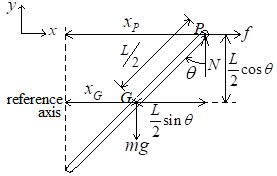
N is the reaction force on the rod.

G is the mass center of the rod.

The displacement from the mass center in the x -direction is measured with respect to the reference axis, xG.

The displacement from the mass center in the y -direction is measured with respect to the horizontal axis through point, P, yG.

The distance between the reference axis and the point P is known.

Equations describing the translational motion:

In the x -direction,

fx=maGx

The acceleration for the translational motion is v˙, where v is the velocity of the rod.

v=x˙v˙=x¨

fx=maGxfx=mv˙fx=mx¨Gf=mx¨G 1

From the free body diagram, an expression is found for xG in terms of θ.

xG+L2sinθ=xPxG=xPL2sinθ 2

Differentiate equation 2 twice to find an expression for x¨G

xG=xPL2sinθ 2x˙G=x˙PL2cosθ×θ˙x˙G=x˙Pθ˙L2cosθx¨G=x¨Pθ¨L2cosθ+θ˙2L2sinθ 3

Substitute equation 3 in 1

f=mx¨G 1x¨G=x¨Pθ¨L2cosθ+θ˙2L2sinθ 3f=mx¨Pθ¨L2cosθ+θ˙2L2sinθ 4

Substitute the given values, m = 20kg and L = 1.4m in equation 4

f=mx¨Pθ¨L2cosθ+θ˙2L2sinθ 4m=20 L=1.4f=20x¨Pθ¨×1.42cosθ+θ˙2×1.42sinθf=20x¨P20×θ¨×1.42cosθ+20×θ˙2×1.42sinθf=20x¨P14θ¨cosθ+14θ˙2sinθ14θ¨cosθ=20x¨P+14θ˙2sinθf14cosθθ¨=20x¨P+14θ˙2sinθf 5

In the y -direction,

fy=maGy

The acceleration for the translational motion is v˙, where v is the velocity of the rod.

v=y˙v˙=y¨

fy=maGyfy=mv˙fy=my¨GRmg=my¨G 6

From the free body diagram, an expression is found for yG in terms of θ.

From point, P, there is no vertical displacement.

yG=L2cosθ 7

Differentiate equation 7 twice to find an expression for y¨G

yG=L2cosθ 7y˙G=L2sinθ×θ˙y˙G=θ˙L2sinθy¨G=θ¨L2sinθ+θ˙2L2cosθ 8

Using the sum of moments find an expression for the reaction force, R.

Ioω˙=MoIGθ¨=MGIGθ¨=L2cosθ×fL2sinθ×RL2sinθ×R=L2cosθ×fIGθ¨

Mass inertia about the center, G, in the y -direction found using the mass inertia of a hollow cylinder in the y -direction.

IG=mL22

Substitute this in the sum of moments equation to find an expression for R.

L2sinθ×R=L2cosθ×fIGθ¨IG=mL22L2sinθ×R=L2cosθ×fmL22×θ¨LRsinθ=LfcosθmL2θ¨R=LfcosθmL2θ¨Lsinθ 9

Substitute equations 8 and 9 in 6

Rmg=my¨G 6y¨G=θ¨L2sinθ+θ˙2L2cosθ 8 R=LfcosθmL2θ¨Lsinθ 9LfcosθmL2θ¨Lsinθmg=mθ¨L2sinθ+θ˙2L2cosθLfcosθmL2θ¨mgLsinθ=mθ¨L2sinθ×Lsinθ+mθ˙2L2cosθ×Lsinθ2Lfcosθ2mL2θ¨2mgLsinθ=mθ¨L2sin2θ+mθ˙2L2cosθsinθ2Lfcosθ2mgLsinθmθ˙2L2cosθsinθ=mθ¨L2sin2θ+2mL2θ¨mL2sin2θ+2mL2θ¨=2Lfcosθ2mgLsinθmθ˙2L2cosθsinθ 10

Substitute the given values, m = 20kg and L = 1.4m in equation 10

mL2sin2θ+2mL2θ¨=2Lfcosθ2mgLsinθmθ˙2L2cosθsinθ 10m=20 L=1.420×1.42sin2θ+2×20×1.42θ¨=2×1.4×fcosθ2×20×g×1.4sinθ20×θ˙2×1.42cosθsinθ39.2sin2θ+78.4θ¨=2.8fcosθ549.36sinθ39.2θ˙2cosθsinθ 11.

Conclusion:

Equations of motion of the rod in terms of θ:

14cosθθ¨=20x¨P+14θ˙2sinθf39.2sin2θ+78.4θ¨=2.8fcosθ549.36sinθ39.2θ˙2cosθsinθ.

Want to see more full solutions like this?

Subscribe now to access step-by-step solutions to millions of textbook problems written by subject matter experts!

Chapter 3 Solutions

System Dynamics

Ch. 3 - The motor in Figure P3.11 lifts the mass mL by...Ch. 3 - Instead of using the system shown in Figure 3.2.6a...Ch. 3 - Consider the cart shown in Figure P3.13. Suppose...Ch. 3 - Consider the cart shown in Figure P3.13. Suppose...Ch. 3 - Consider the spur gears shown in Figure P3.15,...Ch. 3 - Consider the spur gears shown in Figure P3.15,...Ch. 3 - Derive the expression for the equivalent inertia...Ch. 3 - Prob. 3.18PCh. 3 - The geared system shown in Figure P3.19 represents...Ch. 3 - Prob. 3.20PCh. 3 - Prob. 3.21PCh. 3 - Prob. 3.22PCh. 3 - For the geared system shown in Figure P3.23,...Ch. 3 - For the geared system discussed in Problem 3.23,...Ch. 3 - The geared system shown in Figure P3.25 is similar...Ch. 3 - Consider the rack-and-pinion gear shown in Figure...Ch. 3 - The lead screw (also called a power screw or a...Ch. 3 - Prob. 3.29PCh. 3 - Derive the equation of motion of the block of mass...Ch. 3 - Assume the cylinder in Figure P3.31 rolls without...Ch. 3 - Prob. 3.33PCh. 3 - Prob. 3.34PCh. 3 - A slender rod 1.4 m long and of mass 20 kg is...Ch. 3 - Prob. 3.36PCh. 3 - Prob. 3.37PCh. 3 - The pendulum shown in Figure P3.38 consists of a...Ch. 3 - Prob. 3.39PCh. 3 - A single link of a robot arm is shown in Figure...Ch. 3 - 3.41 It is required to determine the maximum...Ch. 3 - Figure P3.42 illustrates a pendulum with a base...Ch. 3 - Figure P3.43 illustrates a pendulum with a base...Ch. 3 - 3.44 The overhead trolley shown in Figure P3.44 is...Ch. 3 - Prob. 3.45PCh. 3 - The “sky crane” shown on the text cover was a...
Knowledge Booster
Background pattern image
Mechanical Engineering
Learn more about
Need a deep-dive on the concept behind this application? Look no further. Learn more about this topic, mechanical-engineering and related others by exploring similar questions and additional content below.
Recommended textbooks for you
Text book image
Elements Of Electromagnetics
Mechanical Engineering
ISBN:9780190698614
Author:Sadiku, Matthew N. O.
Publisher:Oxford University Press
Text book image
Mechanics of Materials (10th Edition)
Mechanical Engineering
ISBN:9780134319650
Author:Russell C. Hibbeler
Publisher:PEARSON
Text book image
Thermodynamics: An Engineering Approach
Mechanical Engineering
ISBN:9781259822674
Author:Yunus A. Cengel Dr., Michael A. Boles
Publisher:McGraw-Hill Education
Text book image
Control Systems Engineering
Mechanical Engineering
ISBN:9781118170519
Author:Norman S. Nise
Publisher:WILEY
Text book image
Mechanics of Materials (MindTap Course List)
Mechanical Engineering
ISBN:9781337093347
Author:Barry J. Goodno, James M. Gere
Publisher:Cengage Learning
Text book image
Engineering Mechanics: Statics
Mechanical Engineering
ISBN:9781118807330
Author:James L. Meriam, L. G. Kraige, J. N. Bolton
Publisher:WILEY
How to balance a see saw using moments example problem; Author: Engineer4Free;https://www.youtube.com/watch?v=d7tX37j-iHU;License: Standard Youtube License