
Manufacturing Engineering & Technology
7th Edition
ISBN: 9780133128741
Author: Serope Kalpakjian, Steven Schmid
Publisher: Prentice Hall
expand_more
expand_more
format_list_bulleted
Concept explainers
Videos
Textbook Question
Chapter 21, Problem 64QTP
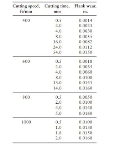
The following flank wear data were collected in a series of machining tests, using C6 carbide tools on 1045 steel (HB = 192). The feed rate was 0.015 in./rev, and the width of cut was 0.030 in. (a) Plot flank wear as a function of cutting time. Using a 0.015 in. wear land as the criterion of tool failure, determine the lives for the two cutting speeds. (b) Plot your results on log–log plot and determine the values of n and C in the Taylor tool-life equation. (Assume a straight line relationship.) (c) Using these results, calculate the tool life for a cutting speed of 300 ft/min.
Expert Solution & Answer
Want to see the full answer?
Check out a sample textbook solution
Students have asked these similar questions
A number of through holes with 10-mm-diameter have been drilled through 30-mm thick cast iron plate. At a
cutting speed of 25 m/min, the high-speed steel drill tool lasted for 44 holes. But, when the cutting speed
increased to 35 m/min, the drill tool lasted for only five holes. The feed used in the both cases is 0.08 mm/rev.
Determine the values of n and Cin the Taylor tool life equation for the data, where cutting speed v is expressed
in m/min, and tool life T is expressed in min.
In turning of stales steel alloy, 1100 mm length and 400 mm diameter, the Feed was 0.35 mm/rev, and depth
of cut = 2.5 mm. The tool used in this cutting is cemented carbide tool where Taylor tool life parameters are n
= 0.24 and C = 450 (tool life (min) and cutting speed (m/min). Compute the cutting speed that will allow the
tool life to be 10% longer than the machining time for this part.
In an orthogonal cutting test with a bar of 75 mm diameter is reduced to 73 mm by using a HSS tool with arake angle = 10o, following observations were made: length of the chip, lc = 69.44 mm, cutting ratio r =0.3, the horizontal component of the cutting force, FH = 1450 N, and the vertical component of the cuttingforce, FV = 850 N. The various parameters recorded in this cutting operation are: depth of cut, d = 2 mm;feed rate, f = 0.3 mm/rev, cutting speed, V = 60 m/min. Using Merchant’s theory calculate the following:1) Friction force along rake face2) Normal force acting on rake face3) Shear force along the shear plane4) Normal force acting on shear plane5) The percentage error in shear angle predicted by Merchant’s theory6) Shear velocity7) Chip velocity8) Total work done9) The shear work proportion out of the total work done10) The friction work proportion out of the total work done
Chapter 21 Solutions
Manufacturing Engineering & Technology
Ch. 21 - Explain why continuous chips are not necessarily...Ch. 21 - Name the factors that contribute to the formation...Ch. 21 - What is the cutting ratio? Is it always less than...Ch. 21 - Explain the difference between positive and...Ch. 21 - Explain how a dull tool can lead to negative rake...Ch. 21 - Comment on the role and importance relief angle.Ch. 21 - Explain the difference between discontinuous chips...Ch. 21 - Why should we be interested in the magnitude of...Ch. 21 - What are the differences between orthogonal and...Ch. 21 - What is a BUE? Why does it form?
Ch. 21 - Is there any advantage to having a built-up edge...Ch. 21 - What is the function of chip breakers? How do they...Ch. 21 - Identify the forces involved in a cutting...Ch. 21 - Explain the characteristics of different types of...Ch. 21 - List the factors that contribute to poor surface...Ch. 21 - Explain what is meant by the term machinability...Ch. 21 - What is shaving in machining? When would it be...Ch. 21 - List reasons that machining operations may be...Ch. 21 - Are the locations of maximum temperature and...Ch. 21 - Is material ductility important for machinability?...Ch. 21 - Explain why studying the types of chips produced...Ch. 21 - Prob. 22QLPCh. 21 - Tool life can be almost infinite at low cutting...Ch. 21 - Explain the consequences of allowing temperatures...Ch. 21 - The cutting force increases with the depth of cut...Ch. 21 - Why is it not always advisable to increase the...Ch. 21 - What are the consequences if a cutting tool chips?Ch. 21 - What are the effects of performing a cutting...Ch. 21 - Prob. 29QLPCh. 21 - Prob. 30QLPCh. 21 - Prob. 31QLPCh. 21 - Prob. 32QLPCh. 21 - Comment on your observations regarding Figs. 21.1...Ch. 21 - Prob. 34QLPCh. 21 - Comment on your observations regarding the...Ch. 21 - Why does the temperature in cutting depend on the...Ch. 21 - You will note that the values of a and b in Eq....Ch. 21 - Prob. 38QLPCh. 21 - Prob. 39QLPCh. 21 - Explain whether it is desirable to have a high or...Ch. 21 - The Taylor tool-life equation is directly...Ch. 21 - Prob. 42QLPCh. 21 - Why are tool temperatures low at low cutting...Ch. 21 - Can high-speed machining be performed without the...Ch. 21 - Prob. 45QLPCh. 21 - Prob. 46QLPCh. 21 - State whether or not the following statements are...Ch. 21 - Let n = 0.5 and C = 400 in the Taylor equation for...Ch. 21 - Assume that, in orthogonal cutting, the rake angle...Ch. 21 - Prob. 50QTPCh. 21 - Prob. 51QTPCh. 21 - Using trigonometric relationships, derive an...Ch. 21 - An orthogonal cutting operation is being carried...Ch. 21 - Prob. 54QTPCh. 21 - Prob. 55QTPCh. 21 - Prob. 56QTPCh. 21 - Show that, for the same shear angle, there are two...Ch. 21 - With appropriate diagrams, show how the use of a...Ch. 21 - In a cutting operation using a 5 rake angle, the...Ch. 21 - For a turning operation using a ceramic cutting...Ch. 21 - In Example 21.3, if the cutting speed V is...Ch. 21 - Using Eq. (21.30), select an appropriate feed for...Ch. 21 - With a carbide tool, the temperature in a cutting...Ch. 21 - The following flank wear data were collected in a...Ch. 21 - The following data are available from orthogonal...Ch. 21 - Prob. 66QTPCh. 21 - Design an experimental setup whereby orthogonal...Ch. 21 - Describe your thoughts on whether chips produced...Ch. 21 - Recall that cutting tools can be designed so that...Ch. 21 - Recall that the chip-formation mechanism also can...Ch. 21 - Prob. 73SDPCh. 21 - Describe your thoughts regarding the recycling of...Ch. 21 - List products that can be directly produced from...Ch. 21 - Obtain a wood planer and some wood specimens. Show...Ch. 21 - It has been noted that the chips from certain...Ch. 21 - As we have seen, chips carry away the majority of...
Knowledge Booster


Learn more about
Need a deep-dive on the concept behind this application? Look no further. Learn more about this topic, mechanical-engineering and related others by exploring similar questions and additional content below.Similar questions
- Puanlar) 16 The outside diameter of a cylinder made of titanium alloy is to be turned. The starting diameter is 400 mm and the length is 1100 mm. The feed is 0.35 mm/rev and the depth of cut is 2.5 mm. The cut will be made with a cemented carbide cutting tool whose Taylor tool life parameters are: n= 0.24 and C=450. Units for the Taylor equation are min for tool life and m/min for cutting speed. Compute the cutting speed that will allow the tool life to be just equal to the cutting time for this part. V vT" = C. %3D Ce Tm 1. %3D 19 fv 25 31 37 43 49 187.9 m/min b) 325.8 m /min 275.8 m/min d) 226.6 m/minarrow_forwardDuring turning tests, using a cemented carbide tool resulted in a 1‑min tool life at a cutting speed = 4.8 m/s and a 22‑min tool life at a speed = 2.0 m/s. (a) Find the n and Carrow_forwardIn a turning operation, cutting speed =200 m/min; feed = 0.25mm mm/rev, and depth of cut = 4.00mm Thermal diffusivity of the work material = 20m mm^2/s and volumetric specific heat =3.5(10^ -3 )J/mm^ 3 -C If the temperature increase above ambient temperature (20degreesC) is the angle measured by a tool-chip thermocouple to be 700degreesC, determine the specific energy for the work material in this operation.arrow_forward
- Q4 Tool life of a turning tool is given by VT0.12xfP.7xd3=C at a cutting speed (V) of 25m/min, feed(f) 0.25 mm/rev and job diameter(d) 4 mm, the tool life was 53 minutes. Calculate (i) Tool life if cutting speed increased by 20 % [3]arrow_forward2. The following data was obtained from an orthogonal cutting test: Rake angle = 20° Cutting speed = 100 m/min Chip length before cutting = 29.4 mm Chip length after cutting = 12.9 mm Vertical cutting force 1050 N Horizontal cutting force = 630 N Using Merchant's analysis, calculate (a) resultant force (c) friction force and friction angle (b) shear plane angle (d) total work donearrow_forwardA mild steel specimen of Initial diameter of 51.5 mm is turned to final diameter of 48 mm for an initial length of 151 mm on a lathe machine. Using the given data find the following. (i) Feed of 0.1 mm/rev & Depth of cut is 0.5 mm (ii) During machining the tool's approach length is 7 mm, over run length is 2mm (iii) Total time required to complete the turning operation is 48.8 minutes (a) Find number of passes to finish the entire turning operation (b) The actual length of the turning operation in mm ( (c)The time required to complete one single turning operation in minutes (d) Spindle speed in rpmarrow_forward
- Low carbon steel having a tensile strength = 300 MPa and a shear strength = 220 MPa is turned at a cutting speed = 2.5 m/s, feed = 0.20 mm/rev and depth of cut = 3.0 mm. The rake angle = 5° in the direction of chip flow. The resulting chip ratio = 0.45. Using the orthogonal model to approximate turning, determine the cutting force and feed force.arrow_forwardA mild steel specimen of Initial diameter of 53.5 mm is turned to final diameter of 47 mm for an initial length of 154 mm on a lathe machine. Using the given data find the following. (i) Feed of 0.4 mm/rev & Depth of cut is 0.5 mm (ii) During machining the tool's approach length is 5 mm, over run length is 2mm (iii) Total time required to complete the turning operation is 59.6 minutesarrow_forwardA mild steel specimen of Initial diameter of 53.5 mm is turned to final diameter of 47 mm for an initial length of 154 mm on a lathe machine. Using the given data find the following. (i) Feed of 0.4 mm/rev & Depth of cut is 0.5 mm (ii) During machining the tool's approach length is 5 mm, over run length is 2mm (iii) Total time required to complete the turning operation is 59.6 minutes (a) Find number of passes to finish the entire turning operation ( (b) The actual length of the turning operation in mm ('arrow_forward
- A turning operation is performed on C1008 steel (a ductile steel) using a tool with a nose radius= 1.3 mm. Cutting speed = 61 m/min and feed = 0.27 mm/rev. Compute an estimate of the surface roughness in this operation. (Hint: the ratio of actual to ideal roughness can be read on the figure below) Equations used; Ra Ri Actual Ratio Theoretical 32NR = rai Ri 2.4 2.2 2.0 1.8 1.6 1.4 1.2 1.0 0 Ductile metals Cast irons Free machining alloys. 100 30.5 200 Cutting speed-ft/min 61 Cutting speed - m/min 300 91.5 400 122arrow_forwardQuestion 3. A cemented carbide tool is used to turn a part with length = 18.0 in and diameter = 3.0 in. The parameters in the Taylor equation are: n= 0.27 and C = 1200. The rate for the operator and machine tool = $33.00/hr, and the tooling cost per cutting edge = $2.00. It takes 3.0 min to load and unload the workpart and 1.50 min to change tools. The feed = 0.013 in/rev. Determine: a) Cutting speed for maximum production rate, b) Tool life in min of cutting, and c) Cycle time and cost per unit of product.arrow_forwardA mild steel specimen of Initial diameter of 30.5 mm is turned to final diameter of 27 mm for an initial length of 153 mm on a lathe machine. Using the given data find the following. (i) Feed of 0.4 mm/rev & Depth of cut is 0.5 mm (ii)During machining the tool's approach length is 5 mm, over run length is 2mm (iii) Time required to complete one single turning operation is 3.5 minutes (a)Find number of passes to finish the entire turning operation (b) Total time required to complete the turning operation in minutesarrow_forward
arrow_back_ios
SEE MORE QUESTIONS
arrow_forward_ios
Recommended textbooks for you
 Elements Of ElectromagneticsMechanical EngineeringISBN:9780190698614Author:Sadiku, Matthew N. O.Publisher:Oxford University Press
 Mechanics of Materials (10th Edition)Mechanical EngineeringISBN:9780134319650Author:Russell C. HibbelerPublisher:PEARSON
 Thermodynamics: An Engineering ApproachMechanical EngineeringISBN:9781259822674Author:Yunus A. Cengel Dr., Michael A. BolesPublisher:McGraw-Hill Education
 Control Systems EngineeringMechanical EngineeringISBN:9781118170519Author:Norman S. NisePublisher:WILEY
 Mechanics of Materials (MindTap Course List)Mechanical EngineeringISBN:9781337093347Author:Barry J. Goodno, James M. GerePublisher:Cengage Learning
 Engineering Mechanics: StaticsMechanical EngineeringISBN:9781118807330Author:James L. Meriam, L. G. Kraige, J. N. BoltonPublisher:WILEY
Elements Of Electromagnetics
Mechanical Engineering
ISBN:9780190698614
Author:Sadiku, Matthew N. O.
Publisher:Oxford University Press
Mechanics of Materials (10th Edition)
Mechanical Engineering
ISBN:9780134319650
Author:Russell C. Hibbeler
Publisher:PEARSON
Thermodynamics: An Engineering Approach
Mechanical Engineering
ISBN:9781259822674
Author:Yunus A. Cengel Dr., Michael A. Boles
Publisher:McGraw-Hill Education
Control Systems Engineering
Mechanical Engineering
ISBN:9781118170519
Author:Norman S. Nise
Publisher:WILEY
Mechanics of Materials (MindTap Course List)
Mechanical Engineering
ISBN:9781337093347
Author:Barry J. Goodno, James M. Gere
Publisher:Cengage Learning
Engineering Mechanics: Statics
Mechanical Engineering
ISBN:9781118807330
Author:James L. Meriam, L. G. Kraige, J. N. Bolton
Publisher:WILEY
The Most Common Metal Machining Processes (Metal Machining Video 1); Author: Sofeast Ltd;https://www.youtube.com/watch?v=uxVJ3qtezGw;License: Standard YouTube License, CC-BY
Machining process and Machine Tools; Author: Amar Gandhi;https://www.youtube.com/watch?v=X2mUJ8baaE0;License: Standard Youtube License