
Concept explainers
Videos
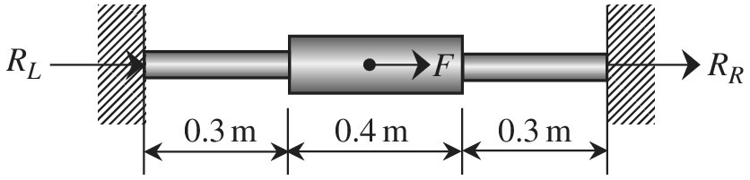
The stepped bar shown in the figure is subjected to a force at the center. Use the finite element method to determine the displacement field
Want to see the full answer?
Check out a sample textbook solution
Chapter 2 Solutions
Introduction To Finite Element Analysis And Design


- Analyse the statically determinate bar illustrated below by expressing the loading as a single function using Macaulay brackets and the Dirac delta, integrating to find th axial force and integrating again to find the displacements, applying the boundary conditions appropriately. Find the axial force in the bar at point A and the displaceme at point B. The cross section of the bar is constant with EA = 18000 kN. a = 4 m, b = 2 m, c = 2 m and d = 4 m. w1 = 12 kN/m, w2 = 17 kN/m,, P1 = 12 kN and P2 = 19kN. a W1 L/2 W2 Multiple Choice Answers Multiple Choice Answer: Axial force at point A (kN, tension positive): a. 3.31 b. 31.97 c. 37.33 d. 31 Multiple Choice Answer: Displacement at point B (mm, positive to right): a. 0.0061 b. 0.0395 c. 0.0193 d. 0.0261 Axial force at point A (kN, tension positive): Displacement at point B (mm, positive to right): L/2 P1 P2 (type in your multiple choice answer, e.g. a, b, c or d) (type in your multiple choice answer, e.g. a, b, c or d)arrow_forwardThe 10 kN load is applied at the free end of the bar as shown in Figure Q4. Let modulus of elasticity E = 200 GPa, the shear modulus G= 80 GPa, and the Poisson's ratio v=0.3. The diameter of the bar is 40 mm. a) Determine the displacement in -y direction of end D by using Castigliano's second theorem. b) Determine the rotation about x' axis of end D by using Castigliano's second theorem. c) Without any calculation, explain whether the rotation about x' axis of end D increases if the applied load is increased from 10 kN to 20 kN. Consider the strain energy due to axial, bending and torsion only. Neglect the strain energy due to transverse shear. B D 10 kN 200 mm 150 mm- 150 mmarrow_forwardDont Copy from chegg need step wise step and correct answers only Use Finite Elemental method Assemble element stiffness matrix for the member of plane frame shown in Figure is oriented at angle 30° to the x-axis. Take E= 200 GPa, I=4 × 10⁶ m* and A = 4 × 10-³m². ,if it 5m 30arrow_forward
- 3. 2 ft 1106 2 ft B ww Cord AB is 2 ft long, the force P = 76 lb, the angle 0 = 56 degrees and the spring's stiffness is k = 56 Ib/ft.arrow_forwardtol F = Fe F= F + F COs # F F sin a. # tan Example (L):Find the two components of the force (100 X) if: 0 = 30, 120 270° as shown in figure. F = 100 N F = 100 N 6%330 6 =120° 0 =270° 0 = 300 0 60 F = 100 N ution:arrow_forwardSuppose that the following rod system is subjected to a specific amount of load that makes the displacements of nodes 2 and 3 to be q2=2.18 mm and q3=0.32 mm. The system is made of a material with Young's modulus of E=150 GPa. Suppose that the vector B (strain-displacement vector) for node 1 is B 1 = 14.9 × [ - 1 . 5 2 - 0 . 5 ] 1/m. Workout the stress of node 1 in GPa. aarrow_forward
- Consider the following spring system. 直一 m, 2 with spring constants c = 5 Assume down is the positive direction. Write the elongation matrix A = Write the stiffness matrix K =arrow_forwardFigure Q4(a) shows the stress-strain curves of material A and material B. A circular rod of material A (diameter 3 cm, length 10 cm) is bonded to a circular rod of material B (diameter 4 cm, length 20 cm) as shown in Figure Q4(b). a) Based on the stress-strain curves shown determine the yield stress (σy) and the elastic modulus (E) of material A and material B.b) Assuming that the bond is rigid, determine the force P required to stretch the composite rod by 0.3 mm?c) Assuming a Poisson’s ratio value of 0.33, determine the change in diameter of the rod made from material B for the same P as determined in part (b).arrow_forwardThe dimensions are of the graph are d1 = 7 cm , L1 = 6 m , d2 = 4.2 cm , and L2 = 5 m with applied loads F1 = 130 kN and F2 = 60 kN . The modulus of elasticity is E = 80 GPa . Use the following steps to find the deflection at point D. Point B is halfway between points A and C. What is the reaction force at A? Let a positive reaction force be to the right.arrow_forward
- For the cantilever plane truss in the figure above, use MATLAB to determine: 1)Nodal displacements 2)Reaction Forces 3)Element Strains and Stresses Assuming that both supports are going to be fixed and the values of E = 70 GPa and A = 0.003125arrow_forwardGiven the stress tensor: Find: 3 36 27 0 σ = 27-36 00 0 18 (a) The components of the traction (force per unit area) acting on a plane with unit normal n= 2 21 3 3'3 T (b) The component of the traction in the direction of the normal (c) The angle between the traction and the normal vector (d) The magnitude of the traction vector (e) The net force acting on a cube with corners at (x,y,z)=(±1,±1,±1)arrow_forward4:50 Step 1 of 7 Done Consider the following diagram showing a rectangular steel bar supporting two overhanging loads: y 300 300 500 400 N 400 N В Bar, b=6, h=32arrow_forward
 Elements Of ElectromagneticsMechanical EngineeringISBN:9780190698614Author:Sadiku, Matthew N. O.Publisher:Oxford University Press
 Mechanics of Materials (10th Edition)Mechanical EngineeringISBN:9780134319650Author:Russell C. HibbelerPublisher:PEARSON
 Thermodynamics: An Engineering ApproachMechanical EngineeringISBN:9781259822674Author:Yunus A. Cengel Dr., Michael A. BolesPublisher:McGraw-Hill Education
 Control Systems EngineeringMechanical EngineeringISBN:9781118170519Author:Norman S. NisePublisher:WILEY
 Mechanics of Materials (MindTap Course List)Mechanical EngineeringISBN:9781337093347Author:Barry J. Goodno, James M. GerePublisher:Cengage Learning
 Engineering Mechanics: StaticsMechanical EngineeringISBN:9781118807330Author:James L. Meriam, L. G. Kraige, J. N. BoltonPublisher:WILEY