
Concept explainers
Videos
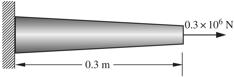
A tapered bar with circular cross section is fixed at
Want to see the full answer?
Check out a sample textbook solution
Chapter 2 Solutions
Introduction To Finite Element Analysis And Design
Additional Engineering Textbook Solutions
Thinking Like an Engineer: An Active Learning Approach (3rd Edition)
Automotive Technology: Principles, Diagnosis, And Service (6th Edition) (halderman Automotive Series)
Fundamentals Of Thermodynamics
Applied Statics and Strength of Materials (6th Edition)
Engineering Mechanics: Statics
Engineering Mechanics: Statics


- Solve the preceding problem if the cross- sectional dimensions are b = 1.5 in. and h = 5.0 in., the gage angle is ß = 750, the measured strains are = 209 × 10-6 and B = -110 × 10, and the material is a magnesium alloy with modulus E = 6.0 X 10⁶ psi and Poisson’s ratio v = 0.35.arrow_forwardA bungee cord that behaves linearly elastically has an unstressed length L0= 760 mm and a stiffness k = 140 N/m. The cord is attached to two pegs, distance/? = 380 mm apart, and is pulled at its midpoint by a Force P = 80 N (see figure). (a) How much strain energy U is stored in the cord? (b) What is the displacement Scof the point where the load is applied? (c) Compare the strain energy (with the quantity PSC12. Note: The elongation of the cord is not small compared lo its original length.arrow_forwardA uniformly tapered lube AB of circular cross section and length L is shown in the figure. The average diameters at the ends are dAand d£= 2d t. Assume E is constant. Find the elongation S of the tube when it is subjected to loads P acting at the ends. Use the following numerical data:^ = 35 mm, L = WO mm, E = 2.1 GPa. and P = 25 tN. Consider the following cases. (a) A hole of constant diameter dAis drilled from B toward A to form a hollow section of length x - U2. (b) A hole of variable diameter a\.x) is drilled, from B toward A to form a hollow section of length x = L/2 and constant thickness t = dA/20.arrow_forward
- Consider a two-component rod fixed at the left end. The first component (on the left, positioned from z=0 to z=L/2) is a solid rod with a shear modulus of G and radius c1. The second component (on the right, positioned from z=L/2 to z=L) is a hollow pipe fixed to component 1 at z=L/2 with the same shear modulus and outer radius c1, but with an inner radius of c2. A torque of 6To is applied at z=L/2, and a torque of -2To is applied at z=L. What value of c2 is required to make the maximum shear stress equivalent in each component? What is the angle of twist at the free end at z=L?arrow_forwardOf a column of infinite length to points A, B, C and D parallel FA, FB, FC and FD (kN) respectively Using the forces in the directions given in the figure, equivalent resultant force (FEŞ) size and application x and y (m) coordinates of the point find. FA=20 FB=55 FC=35 FD=77 xA=13 yA=8 xB=3 yB=5 xC=10 yC=0 xD=-9 yD=-15arrow_forwardThe bronze bar 2.7 m long with a cross-sectional area of 415 mm2 is placed between two rigid walls. At a temperature of 8.1 °C, there is a gap Δ = 2.32 mm, as shown in the figure. Find the compressive force (in N) experienced by the bar at a temperature of 68.66 °C. Use α = 18 × 10-6 /°C and E = 80.71 GPa. Round off your answer to three decimal places.arrow_forward
- . A thin plate is composed of four CST elements, as shown inthe figure below. The plate is subjected to a uniform tensile traction sacting on the right edge and a concentrated force F at the center. Usethe following values: E = 105 GPa, ν = 0.3, t = 5 mm, L = 400 mm,H = 400 mm, s = 50 MPa, and F = 150 kN.(a) Compute all the nodal displacements.(b) For each element, compute the element stress components σxx, σyy,and τxy.(c) For each element, compute the element planar principal normal stressesσ1′ and σ2′.(d) For each element, compute the Von Mises and Tresca effective stresses. Please help solve using only FEM( Finite Element Method) and the values given, very urgent. Thank you.arrow_forwardQ.2) A brass bar 500 mm long and 100 mm × 100 mm in cross-section is subjected to an axial pull in the direction of its length. If the increase in volume of the bar is 50 mm³, then the magnitude of the pull (kN) will be (Take E = 100 GPa and µ = 0.25) (A) 20 (С) 25 (В) 30 (D) 15arrow_forwardsolve the following for forces and displacement at each of the nodes. where F is 500lb. M is 70 ft.lb; W is 8000 Ib/ft W lb/ft 15 ft 10 ft E= 30 x 10 psi A=5 in.? 1= 200 in. 45° Farrow_forward
- Analyse the statically determinate bar illustrated below by expressing the loading as a single function using Macaulay brackets and the Dirac delta, integrating to find th axial force and integrating again to find the displacements, applying the boundary conditions appropriately. Find the axial force in the bar at point A and the displaceme at point B. The cross section of the bar is constant with EA = 18000 kN. a = 4 m, b = 2 m, c = 2 m and d = 4 m. w1 = 12 kN/m, w2 = 17 kN/m,, P1 = 12 kN and P2 = 19kN. a W1 L/2 W2 Multiple Choice Answers Multiple Choice Answer: Axial force at point A (kN, tension positive): a. 3.31 b. 31.97 c. 37.33 d. 31 Multiple Choice Answer: Displacement at point B (mm, positive to right): a. 0.0061 b. 0.0395 c. 0.0193 d. 0.0261 Axial force at point A (kN, tension positive): Displacement at point B (mm, positive to right): L/2 P1 P2 (type in your multiple choice answer, e.g. a, b, c or d) (type in your multiple choice answer, e.g. a, b, c or d)arrow_forward4. Consider the figure below. Determine the displacement of point F. Assume all the cables are steel with a cross sectional area of 0.3226 m² and Modulus of Elasticity of 200 GPa. 2m Im W B 1.5m +1.5m. F с 90 000 N 2m Im D Imarrow_forwardConsider the two bars of identical material with their elastic modulus E as shown in Figure below. Both bars have the same circular cross-section with diameter of d. The length of the longer bar is 2L and the length of the shorter bar is L. The angle between the bars is B. The system is subjected to a vertical force acting at point Pas shown in the figure with a magnitude of F. Calculate horizontal and vertical components of the displacement of point P. Use engineering notation (ENG display mode on scientific calculators) with 3 significant figures after the decimal point. E (psi) 1.50E+06 d (in) 1.25 L (in) 12 Beta (degrees) 30 F (Ibf) 110 F P L 2Larrow_forward
 Mechanics of Materials (MindTap Course List)Mechanical EngineeringISBN:9781337093347Author:Barry J. Goodno, James M. GerePublisher:Cengage Learning