
Videos
Assume that the two circuits in Fig. 19.135 are equivalent. The parameters of the two circuits must be equal. Using this factor and the z parameters, derive Eqs. (9.67) and (9.68).
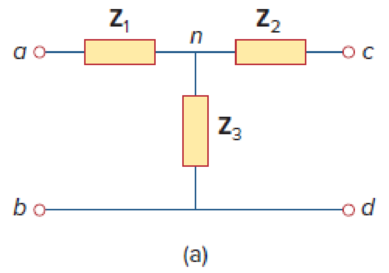
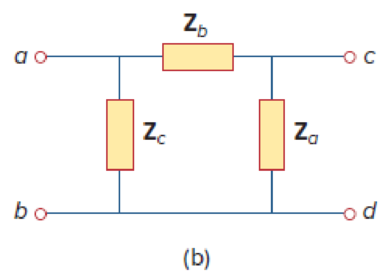
Figure 19.135
Derive the expressions in Equations (9.67) and (9.68) in the textbook.
Explanation of Solution
Given Data:
Refer to Figure 19.135 in the textbook given circuits.
Consider the parameters of two circuits are equal.
Calculation:
Refer to Figure 19.135 (a) in the textbook and write the expression for
Refer to Figure 19.135 (b) in the textbook and write the expression for
From Equation (1), substitute
Refer to Figure 19.135 (a) in the textbook and write the expression for
Refer to Figure 19.135 (b) in the textbook and write the expression for
From Equation (3), substitute
Refer to Figure 19.135 (a) in the textbook and write the expression for
Refer to Figure 19.135 (b) in the textbook and write the expression for
From Equation (5), substitute
Subtract Equation (4) from Equation (2) and obtain the expression as follows:
Add Equations (6) and (7) and obtain the expression as follows:
Simplify the expression as follows:
Subtract Equation (8) from Equation (6) and obtain the expression as follows:
Subtract Equation (8) from Equation (2) and obtain the expression as follows:
From Equations (8), (9), and (10), the expressions in Equation (9.68) are derived.
Note that, the obtained expressions are not same as the expressions in the textbook, since the position of the impedances are changed in the given circuits.
Use expressions in Equations (8), (9), and (10) and obtain the expression as follows:
Divide Equation (11) by Equation (8) and obtain the expression as follows:
Divide Equation (11) by Equation (9) and obtain the expression as follows:
Divide Equation (11) by Equation (10) and obtain the expression as follows:
From Equations (12), (13), and (14), the expressions in Equation (9.67) are derived.
Note that, the obtained expressions are not same as the expressions in the textbook, since the position of the impedances are changed in the given circuits.
Conclusion:
Thus, the expressions in Equations (9.67) and (9.68) in the textbook are derived.
Want to see more full solutions like this?
Chapter 19 Solutions
Fundamentals of Electric Circuits


- The professor that invented the strain gage was a professor at what university? Caltech University University of Michigan MIT Oxford Univ. Caregie Mellon Universityarrow_forwardWhich of the following is the expression defining the given circuit? (Z and A are LSB. U1 is 8x1 multiplexer integrated.)arrow_forwardDerive the expressions for iL(t) and vc(t) in switching circuits shown below. Assume all initial conditions are zero. Use Vdc = 20 V, Idc = 2 A, R = 200 Ω, C = 0.01 μF, and L = 2 mH, sketch iL and vC. ..arrow_forward
- Calculate the S parameters of the following networkarrow_forwardThe h parameters for the two-port amplifier circuit are h11=500 Ω;h12=10−3;h21=50;h22=50 μS. The internal impedance of the source is 1500+j0 Ω, and the loadimpedance is 10,000+j0 Ω. The ideal voltage source is generating avoltagevg=250 cos 40,000t mV. Find the average power delivered to ZL.arrow_forwardConsider the input signal to an LTI system as x(t)= etu(−t).If the output to the system is measured as y(t)=e-tsint u(t) + e-tu(t) + 2etu(-t) a) sketch the pole-zero plot b)Is the system causal and stable?Just if your answersarrow_forward
- 11.a. The maximum number of lines of resolution of an encoder that’s used with a three-phase stepper motorisA. 5000.B. 20,000.C. 10,000.D. 15,000. 11.b. A bipolar stepper motor has how many wire leads exiting from the motor?A. 4B. 6C. 2D. 8arrow_forwardparameter with yourselfarrow_forwardI need help understanding this question.. Write the mesh equations for the network Fig.18.68. Determine the current through the resistor R1.arrow_forward
- Derive the expression for the input impedance, Zin=V1/I1 for thecircuit in terms of the b parameters.arrow_forward8.17 MECT361 Mechatronics Components and Instrumentation Prove Equation 8.14. 8.14. Visit Microchip’s website ( www.microchip.com ) and find specifications for the MCP32X series of A/D converters. What is their resolution? What type of architec- ture is used in obtaining the binary representation of the analog value? PLEASE GIVE ME THE REFRENCE I Will get zero if you didn't put the refrencearrow_forwardThis is a review question of second order LTI system, solve for the poles. Consider the circuit below where RA=RB=10k R1=R2=1k C1=C2=2uF Compute for the poles.arrow_forward
 Introductory Circuit Analysis (13th Edition)Electrical EngineeringISBN:9780133923605Author:Robert L. BoylestadPublisher:PEARSON
 Delmar's Standard Textbook Of ElectricityElectrical EngineeringISBN:9781337900348Author:Stephen L. HermanPublisher:Cengage Learning
 Programmable Logic ControllersElectrical EngineeringISBN:9780073373843Author:Frank D. PetruzellaPublisher:McGraw-Hill Education
 Fundamentals of Electric CircuitsElectrical EngineeringISBN:9780078028229Author:Charles K Alexander, Matthew SadikuPublisher:McGraw-Hill Education
 Electric Circuits. (11th Edition)Electrical EngineeringISBN:9780134746968Author:James W. Nilsson, Susan RiedelPublisher:PEARSON
 Engineering ElectromagneticsElectrical EngineeringISBN:9780078028151Author:Hayt, William H. (william Hart), Jr, BUCK, John A.Publisher:Mcgraw-hill Education,