
Concept explainers
Videos
A two-stage amplifier in Fig. 19.134 contains two identical stages with
If ZL = 20 kΩ, find the required value of Vs to produce Vo = 16 V.
![Chapter 19, Problem 98P, A two-stage amplifier in Fig. 19.134 contains two identical stages with [h]=2k0.004200500S If ZL =](http://dev-ingestion-image-output.s3-website-us-east-1.amazonaws.com/9780078028229/Chapter-19/images/28229-19-98p-question-digital_image_001.png)
Figure 19.134
Calculate the required source voltage for the given two-stage amplifier.
Answer to Problem 98P
The required source voltage for the given two-stage amplifier is
Explanation of Solution
Given Data:
The h parameters of each stage of the amplifier are given as follows:
The load impedance and output voltage of the given two-stage amplifier are given as follows:
Refer to Figure 19.134 in the textbook for the given two-stage amplifier circuit.
Formula used:
Refer to TABLE 19.1 in the textbook, write the expression for transmission parameters in terms of h parameters as follows:
Write the expression for
Write the expression for
From TABLE 19.1 in the textbook, write the expression for impedance parameters in terms of transmission parameters as follows:
Calculation:
From the given circuit, the two-stage amplifier is the cascade connection of two identical transistors. Obtain the transmission parameters for two-stage amplifier and then convert into impedance parameters for simple analysis.
Find the transmission parameters for one stage of the two-stage amplifier as follows:
Substitute
Substitute
As both the stages are identical, the transmission parameters of second stage of the amplifier are equal to the first stage.
As the two identical stages are connected in cascade to form a two-stage amplifier, write the expression for overall transmission parameters for the amplifier as follows:
Substitute
From the obtained transmission parameters of the two-stage amplifier, write the transmission parameters as follows:
Convert the obtained transmission parameters into impedance parameters as follows:
Substitute
Substitute
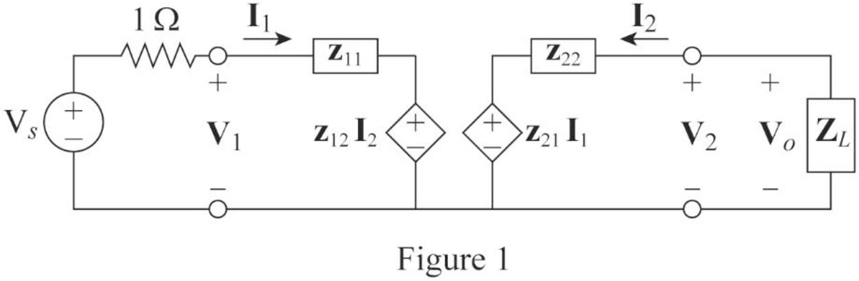
Refer to Figure 19.5 (b) in the textbook for general equivalent circuit of impedance parameters and draw the circuit for given amplifier as shown in Figure 1.
From the circuit in Figure 1, apply KVL to the input loop as follows:
Simplify the expression as follows:
From the circuit in Figure 1, apply KVL to the output loop as follows:
Simplify the expression as follows:
From Figure 1, write the expression for
Rearrange the expression as follows:
Substitute
From Equations (7) and (8), substitute
Substitute
Simplify the expression as follows:
Conclusion:
Thus, the required source voltage for the given two-stage amplifier is
Want to see more full solutions like this?
Chapter 19 Solutions
Fundamentals of Electric Circuits


- Practice Problem 19.6 h = 2 kΩ h12 = 104 h₂1 = 100 h22 = 10-5 S Zin Figure 19.27 For Practice Prob. 19.6. www 50 ΚΩ Find the impedance at the input port of the circuit in Fig. 19.27. Answer: 1.6667 kN.arrow_forwardonics-I || Spring21 For the transistor circuit shown below, if the transistor is in cutoff, then Ic is given by: Vcc RC RB VCE O Vcc/Rc O (Vcc-VBc)/Rc O B*le O Zero ype here to searcharrow_forwardAn amplifier is described by the following two port parameters: Rm = 80KM, Ri = 2K and Ro= 1000. Determine Gm. Show your work!arrow_forward
- 12 Prob.19. Find - (i) Z-parameters (ü) Y-parameters. 52 V1 V 2 05 Varrow_forwardPractice Problem 19.6 Find the impedance at the imput port of the circuit in Fig. 19.27. =2 k Answer: 1.6667 kl. = 100 b= 10s 50 ka Figure 19.27 For Practice Prob. 19.6. rircut in F: 19.28arrow_forwardPractice Problem 19.6 Find the impedance at the input port of the cicuit in Fig. 19.27. Answer: 1.6667 kfl. b =2 ka = 10 b = 100 = 10s 30 ka Figure 19.27 For Practice Prob. 19.6.arrow_forward
- Obtain the parameter H12arrow_forwardvariable conversion elements are used to improve the quality of the output of a measurement system. Select one: O True O Falsearrow_forwardQuestion 1 From the circuit in Figure 1, determine the impedance and hybrid parameters of the two-port network in s-domain. 5Н 3 H 4Ω 0.5F Figure 1arrow_forward
- In the following CE amplifier with the following values given: A) Calculate the appropriate capacitor Cc for FL=100Hz . B) Get the gain of the middle band, its input and output resistance. β=hfe=100gm=100mA/VRB=R1||R2=50KΩRs=1KΩRE=1.5KΩarrow_forwardQ.1: Assume ß = ∞ (Ignore base current) 10 V • Find all the DC currents, voltages, and Ipc • Draw small-signal and find |Aya| = | Find VeM, VCM 4k 4k %3D Vo o o Voz Vid 8k Max yMin Vid/2 o Q1 4k Q3 6k 2.65k - 10 Varrow_forwardLet hi[n] represent the nth sample of the unit-sample response of a system with system functional H(R). Determine hi[2] and hi[119] for each of the following systems: R 1-3/R a. H₁(R)arrow_forward
 Introductory Circuit Analysis (13th Edition)Electrical EngineeringISBN:9780133923605Author:Robert L. BoylestadPublisher:PEARSON
 Delmar's Standard Textbook Of ElectricityElectrical EngineeringISBN:9781337900348Author:Stephen L. HermanPublisher:Cengage Learning
 Programmable Logic ControllersElectrical EngineeringISBN:9780073373843Author:Frank D. PetruzellaPublisher:McGraw-Hill Education
 Fundamentals of Electric CircuitsElectrical EngineeringISBN:9780078028229Author:Charles K Alexander, Matthew SadikuPublisher:McGraw-Hill Education
 Electric Circuits. (11th Edition)Electrical EngineeringISBN:9780134746968Author:James W. Nilsson, Susan RiedelPublisher:PEARSON
 Engineering ElectromagneticsElectrical EngineeringISBN:9780078028151Author:Hayt, William H. (william Hart), Jr, BUCK, John A.Publisher:Mcgraw-hill Education,