
Fundamentals of Electric Circuits
6th Edition
ISBN: 9780078028229
Author: Charles K Alexander, Matthew Sadiku
Publisher: McGraw-Hill Education
expand_more
expand_more
format_list_bulleted
Videos
Textbook Question
Chapter 19, Problem 13P
Determine the average power delivered to ZL = 5 + j4 in the network of Fig. 19.74. Note: The voltage is rms.
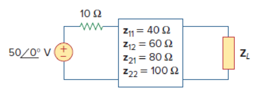
Figure 19.74
Expert Solution & Answer
Want to see the full answer?
Check out a sample textbook solution
Students have asked these similar questions
Problem 1:
Obtain the input impedance by replacing the linear transformer by its T equivalent.
/100
802
Z
1402 252
m
www
/30
2002
-160
What should ZL be for the maximum power transfer in the circuit given below and calculate the maximum power
QI:
If the 2-stage Marx impulse generator circuit shown below is supplied by a DC voltage
source of 140 kV:
a. Which
gap
should be the smallest? Why?
b. Find the voltages VA, VB, Vc and Vp for the points A, B, C and D when the two spark
gaps trigger.
c. Re-draw the circuit, with showing the values of voltages for the capacitors 1 and 2 and
their polarities.
d. If the voltage drop of each stage is 10 kV, find the output peak voltage (Vp) that is used
testing.
e. Find the efficiency for the circuit.
f. Repeat d and e above if the generator is consisting of 3 stages.
R1
R1
DC Voltage G1
G2
VO
- C2
D
RO
R2
R2
VP
Chapter 19 Solutions
Fundamentals of Electric Circuits
Ch. 19.2 - Find the z parameters of the two-port network in...Ch. 19.2 - Calculate I1 and I2 in the two-port of Fig. 19.11....Ch. 19.3 - Obtain the y parameters for the T network shown in...Ch. 19.3 - Obtain the y parameters for the circuit in Fig....Ch. 19.4 - Determine the h parameters for the circuit in Fig....Ch. 19.4 - Find the impedance at the input port of the...Ch. 19.4 - For the ladder network in Fig. 19.30, determine...Ch. 19.5 - Find the transmission parameters for the circuit...Ch. 19.5 - Prob. 9PPCh. 19.6 - Determine [y] and [T] of a two-port network whose...
Ch. 19.6 - Find the z parameters of the op amp circuit in...Ch. 19.7 - Find V2/Vs in the circuit in Fig. 19.43. Figure...Ch. 19.7 - Obtain the y parameters for the network in Fig....Ch. 19.7 - Obtain the ABCD parameter representation of the...Ch. 19.8 - Obtain the h parameters for the network in Fig....Ch. 19.8 - Obtain the z parameters of the circuit in Fig....Ch. 19.9 - For the transistor amplifier of Fig. 19.60, find...Ch. 19.9 - Prob. 18PPCh. 19 - For the single-element two-port network in Fig....Ch. 19 - For the single-element two-port network in Fig....Ch. 19 - For the single-element two-port network in Fig....Ch. 19 - For the single-element two-port network in Fig....Ch. 19 - For the single-element two-port network in Fig....Ch. 19 - For the single-element two-port network in Fig....Ch. 19 - When port 1 of a two-port circuit is...Ch. 19 - A two-port is described by the following...Ch. 19 - If a two-port is reciprocal, which of the...Ch. 19 - Prob. 10RQCh. 19 - Obtain the z parameters for the network in Fig....Ch. 19 - Find the impedance parameter equivalent of the...Ch. 19 - Find the z parameters of the circuit in Fig....Ch. 19 - Using Fig. 19.68, design a problem to help other...Ch. 19 - Obtain the z parameters for the network in Fig....Ch. 19 - Compute the z parameters of the circuit in Fig....Ch. 19 - Calculate the z parameters of the circuit in Fig....Ch. 19 - Find the z parameters of the two-port in Fig....Ch. 19 - The y parameters of a network are:...Ch. 19 - Construct a two-port that realizes each of the...Ch. 19 - Determine a two-port network that is represeted by...Ch. 19 - For the circuit shown in Fig. 19.73, let z=106412...Ch. 19 - Determine the average power delivered to ZL = 5 +...Ch. 19 - For the two-port network shown in Fig. 19.75, show...Ch. 19 - For the two-port circuit in Fig. 19.76,...Ch. 19 - For the circuit in Fig. 19.77, at = 2 rad/s, z11...Ch. 19 - Prob. 17PCh. 19 - Calculate the y parameters for the two-port in...Ch. 19 - Using Fig. 19.80, design a problem to help other...Ch. 19 - Find the y parameters for the circuit in Fig....Ch. 19 - Obtain the admittance parameter equivalent circuit...Ch. 19 - Obtain the y parameters of the two-port network in...Ch. 19 - (a) Find the y parameters of the two-port in Fig....Ch. 19 - Find the resistive circuit that represents these y...Ch. 19 - Prob. 25PCh. 19 - Calculate [y] for tle two-port in Fig. 19.85.Ch. 19 - Find the y parameters for the Circuit in Fig....Ch. 19 - In the circuit of Fig. 19.65, the input port is...Ch. 19 - In the bridge circuit of Fig. 19.87, I1 = 20 A and...Ch. 19 - Find the h parameters for the networks in Fig....Ch. 19 - Determine the hybrid parameters for the network in...Ch. 19 - Using Fig. 19.90, design a problem to help other...Ch. 19 - Obtain the h parameters for the two-port of Fig....Ch. 19 - Obtain the h and g parameters of the two-port in...Ch. 19 - Determine the h parameters for the network in Fig....Ch. 19 - For the two-port in Fig. 19.94. h=16320.01S Find:...Ch. 19 - The input port of the circuit in Fig. 19.79 is...Ch. 19 - The h parameters of the two-port of Fig. 19.95...Ch. 19 - Obtain the g parameters for the wye circuit of...Ch. 19 - Using Fig. 19.97, design a problem to help other...Ch. 19 - For the two-port in Fig. 19.75, show that...Ch. 19 - The h parameters of a two-port device are given by...Ch. 19 - Find the transmission parameters for the...Ch. 19 - Using Fig. 19.99, design a problem to help other...Ch. 19 - Find the ABCD parameters for the circuit in Fig....Ch. 19 - Find the transmission parameters for the circuit...Ch. 19 - Obtain the ABCD parameters for the network in Fig....Ch. 19 - For a two-port, let A = 4, B = 30 , C = 0.1 S, and...Ch. 19 - Using impedances in the s-domain, obtain the...Ch. 19 - Derive the s-domain expression for the t...Ch. 19 - Obtain the t parameters for the network in Fig....Ch. 19 - (a) For the T network in Fig. 19.106, show that...Ch. 19 - Prob. 53PCh. 19 - Show that the transmission parameters of a...Ch. 19 - Prove that the g parameters can be obtained from z...Ch. 19 - For the network of Fig. 19.107, obtain VoVs....Ch. 19 - Given the transmission parameters T=32017 obtain...Ch. 19 - Design a problem to help other students better...Ch. 19 - Given that g=0.06S0.40.22 determine: (a) [z] (b)...Ch. 19 - Design a T network necessary to realize the...Ch. 19 - For the bridge circuit in Fig. 19.108, obtain: (a)...Ch. 19 - Find the z parameters of the op amp circuit in...Ch. 19 - Determine the z parameters of the two-port in Fig....Ch. 19 - Determine the y parameters at = 1,000 rad/s for...Ch. 19 - What is the y parameter presentation of the...Ch. 19 - In the two-port of Fig. 19.113, let y12 = y21 = 0,...Ch. 19 - If three copies of the circuit in Fig. 19.114 are...Ch. 19 - Obtain the h parameters for the network in Fig....Ch. 19 - The circuit in Fig. 19.116 may be regarded as two...Ch. 19 - For the parallel-series connection of the two...Ch. 19 - Determine the z parameters for the network in Fig....Ch. 19 - A series-parallel connection of two two-ports is...Ch. 19 - Three copies of the circuit shown in Fig. 19.70...Ch. 19 - Determine the ABCD parameters of the circuit in...Ch. 19 - For the individual two-ports shown in Fig. 19.121...Ch. 19 - Use PSpice or MultiSim to obtain the z parameters...Ch. 19 - Using PSpice or MultiSim, find the h parameters of...Ch. 19 - Obtain the h parameters at = 4 rad/s for the...Ch. 19 - Use PSpice or MultiSim to determine the z...Ch. 19 - Use PSpice or MultiSim to find the z parameters of...Ch. 19 - Repeat Prob. 19.26 using PSpice or MultiSim....Ch. 19 - Use PSpice or MultiSim to rework Prob. 19.31....Ch. 19 - Rework Prob. 19.47 using PSpice or MultiSim....Ch. 19 - Using PSpice or MultiSim, find the transmission...Ch. 19 - At =1rad/s, find the transmission parameters of...Ch. 19 - Obtain the g parameters for the network in Fig....Ch. 19 - For the circuit shown in Fig. 19.129, use PSpice...Ch. 19 - Using the y parameters, derive formulas for Zin,...Ch. 19 - A transistor has the following parameters in a...Ch. 19 - A transistor with hfe=120,hie=2khre=104,hoe=20S is...Ch. 19 - For the transistor network of Fig. 19.130,...Ch. 19 - Prob. 92PCh. 19 - Prob. 93PCh. 19 - A transistor in its common-emitter mode is...Ch. 19 - Prob. 95PCh. 19 - Prob. 96PCh. 19 - Synthesize the transfer function...Ch. 19 - A two-stage amplifier in Fig. 19.134 contains two...Ch. 19 - Assume that the two circuits in Fig. 19.135 are...
Knowledge Booster


Learn more about
Need a deep-dive on the concept behind this application? Look no further. Learn more about this topic, electrical-engineering and related others by exploring similar questions and additional content below.Similar questions
- An 800 kV transmission line has a maximum power transfer capacity, P, it is operated at 400 kV with the series reactance unchanged, the new maximum power transfer capacity, is approximatelyarrow_forwardA three phase bridge rectifier has a purely resistive load. The rectifier delivers 45 A current at an average output voltage of Vdc 300 V. The rms output voltage Vrms is equal to: Select one: а. 300.25V O b. 275.5V О с. 180.1V O d. 240.15Varrow_forwardJn EXample 4) : る= 61ん Ic Find : (4) the read , the reactive and the apparent powerdelivered to the load and the load p.f. 6) P, Q and s supplied by the Soure and thearrow_forward
- デジタル形式で段階的に解決 ありがとう!! SOLVE STEP BY STEP IN DIGITAL FORMAT 4. For the circuit in the figure, determine: a) The total impedance ZT in polar form. b) The total current. c) The voltages VR and VC. d) Total power and power factor. + e = 20 sin wt f = 1 kHz ZT + UR + UC R ww 2.2 ΚΩ C HE 0.2 μεarrow_forwardデジタル形式で段階的に解決 ありがとう!! SOLVE STEP BY STEP IN DIGITAL FORMAT 8. For the circuit in the figure: a) Determine the total admittance and impedance in polar form. b) Determine the value of C in microfarads and L in henries. c) Determine the voltage E and the currents IR, IL and IC in phasor form. d) Verify Kirchhoff's current law at a node. e) Determine the power supplied to the circuit. f) Determine the power factor of the circuit, and indicate whether it is leading or lagging. i, = 3 sen(3771 +60°)(D R1.2 XL 20 Xc 50arrow_forwardA tap-changing transformer has an effective impedance of 0.03+j 0.35 Q and serves a load which draws an apparent power of 1.2 MVA with 0.88 lagging power factor. If the voltage at load terminals is 1.9 kV. ▪ Find the voltage at the source side with 115% tap located at the load side.arrow_forward
- 1- Determine YT and ZT 2- Sketch the admittance diagram. 3- Find E and IL. 4- Compute the power factor of the network and the power delivered to the network 5- Determine the equivalent series circuit as far as the terminal charac-teristics of the network are concerned. 6- Using the equivalent circuit developed in part e, calculate E, and compare it with the result of part c. 7- Determine the power delivered to the network, and compare it with the solution of part (d). 8- Determine the equivalent parallel network from the equivalent series circuit, and calculate the total admittance Yr. Compare the result with the solution of part (a). i= √2 (12) sin 1000r ZT R₁100 R₂40 L₁6 mH L12 mH 80 μF 20 µFarrow_forward6. write the. difference epuation and realize the system 2.+ 5. 2+ 2 Z."arrow_forwardThe base impedance and the base voltage for a given power system are 12 Q and 489 V, respectively. The base kVA will be O a. 40.71 O b. 1.00 O c. 19.93 O d. 40.79arrow_forward
- An industrial plant is powered with a delta delta system, along with a transformer bank made up of single-phase transformers of 20KVA, 2300/230 V each. The bank supplies a 40 KVA load with a power factor of 0.7 (-). If a damaged transformer is removed for repair, calculate:a) The load in KVA that each transformer has.b) The nominal load of the transformer bank W.arrow_forward2. For the network below find: i) The load line current. ii) The active power delivered by the load. iii) The apparent power of the source. 127 V 64 mH 15 2 50 Hz SOURCE 15 2 LOAD 64 mH ww 64 mH 15 2arrow_forward12:32 A 15--- 0.1 15- Composed of three sections. The cross-sectional area is D.001m² Lore ta= 0-3m, Is =0-2m , I. = 0. Im, An for each section · he mean cre langh -gap length of O.I mm is cut in the cina- Mr. for sections aibic are 5000, 1000 and 10,000mespectively. Flux in the air End J mmf zeluctances of the sections. Aiu is 7.5x10"lb gap ü) exciting Curent in the coil has 100 turns End I Recommendedarrow_forward
arrow_back_ios
SEE MORE QUESTIONS
arrow_forward_ios
Recommended textbooks for you
 Introductory Circuit Analysis (13th Edition)Electrical EngineeringISBN:9780133923605Author:Robert L. BoylestadPublisher:PEARSON
 Delmar's Standard Textbook Of ElectricityElectrical EngineeringISBN:9781337900348Author:Stephen L. HermanPublisher:Cengage Learning
 Programmable Logic ControllersElectrical EngineeringISBN:9780073373843Author:Frank D. PetruzellaPublisher:McGraw-Hill Education
 Fundamentals of Electric CircuitsElectrical EngineeringISBN:9780078028229Author:Charles K Alexander, Matthew SadikuPublisher:McGraw-Hill Education
 Electric Circuits. (11th Edition)Electrical EngineeringISBN:9780134746968Author:James W. Nilsson, Susan RiedelPublisher:PEARSON
 Engineering ElectromagneticsElectrical EngineeringISBN:9780078028151Author:Hayt, William H. (william Hart), Jr, BUCK, John A.Publisher:Mcgraw-hill Education,
Introductory Circuit Analysis (13th Edition)
Electrical Engineering
ISBN:9780133923605
Author:Robert L. Boylestad
Publisher:PEARSON
Delmar's Standard Textbook Of Electricity
Electrical Engineering
ISBN:9781337900348
Author:Stephen L. Herman
Publisher:Cengage Learning
Programmable Logic Controllers
Electrical Engineering
ISBN:9780073373843
Author:Frank D. Petruzella
Publisher:McGraw-Hill Education
Fundamentals of Electric Circuits
Electrical Engineering
ISBN:9780078028229
Author:Charles K Alexander, Matthew Sadiku
Publisher:McGraw-Hill Education
Electric Circuits. (11th Edition)
Electrical Engineering
ISBN:9780134746968
Author:James W. Nilsson, Susan Riedel
Publisher:PEARSON
Engineering Electromagnetics
Electrical Engineering
ISBN:9780078028151
Author:Hayt, William H. (william Hart), Jr, BUCK, John A.
Publisher:Mcgraw-hill Education,
Inductors Explained - The basics how inductors work working principle; Author: The Engineering Mindset;https://www.youtube.com/watch?v=KSylo01n5FY;License: Standard Youtube License