
Fundamentals of Electric Circuits
6th Edition
ISBN: 9780078028229
Author: Charles K Alexander, Matthew Sadiku
Publisher: McGraw-Hill Education
expand_more
expand_more
format_list_bulleted
Videos
Textbook Question
Chapter 19, Problem 37P
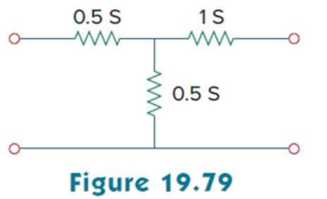
The input port of the circuit in Fig. 19.79 is connected to a 10-V dc voltage source while the output port is termiııated by a 5-Ω resistor. Find the voltage across the 5-Ω resistor by usiııg h parameters of the circuit. Confirm your result by using direct circuit analysis.
Expert Solution & Answer
Want to see the full answer?
Check out a sample textbook solution
Students have asked these similar questions
(a) A voltmeter and an ammeter can be connected as shown in Fig. 19-83a to measure a
resistance R. If V is the voltmeter reading, and / is the ammeter reading, the value of R will not
quite be VI (as in Ohn's law) because some current goes through the voltmeter. Show that the
actual value of Ris
1
I
1
-
R
V
Ry
Where Ry is the voltrneter resistance. Note that R z V/I if Ry > R. (b) A voltmeter
and an ammeter can also be connected as shown in Fig. 19-83b to measure a resistance R.
Show in this case that
V
R
RA,
I
where Vand / are the voltmeter and ammeter readings and Ra is the resistance of the
arnmeter. Note that R = V/I if RA « R.
V
A
A
R
R
(a)
(b)
Find H parameters for the circuit
82
ww
62
ww
oww
42
42
In the parallel connection of the following
two port network, which of the following
is correct
he
Vla
1₁
V₁b
Y11 Y11a / Y11b
Y11=Y11a + Y11b
Y11=Y11a x Y11b
O Y11=Y11a - Y11b
Y
Y₂
V₂0
126
√₂b-
*
Studying of transient is important to
Take in consideration the abnormal cases
which might damage the components
Take in consideration the stable cases so
that to deal well with the system
Take in consideration the steady state case
Take in consideration the components
positions
Chapter 19 Solutions
Fundamentals of Electric Circuits
Ch. 19.2 - Find the z parameters of the two-port network in...Ch. 19.2 - Calculate I1 and I2 in the two-port of Fig. 19.11....Ch. 19.3 - Obtain the y parameters for the T network shown in...Ch. 19.3 - Obtain the y parameters for the circuit in Fig....Ch. 19.4 - Determine the h parameters for the circuit in Fig....Ch. 19.4 - Find the impedance at the input port of the...Ch. 19.4 - For the ladder network in Fig. 19.30, determine...Ch. 19.5 - Find the transmission parameters for the circuit...Ch. 19.5 - Prob. 9PPCh. 19.6 - Determine [y] and [T] of a two-port network whose...
Ch. 19.6 - Find the z parameters of the op amp circuit in...Ch. 19.7 - Find V2/Vs in the circuit in Fig. 19.43. Figure...Ch. 19.7 - Obtain the y parameters for the network in Fig....Ch. 19.7 - Obtain the ABCD parameter representation of the...Ch. 19.8 - Obtain the h parameters for the network in Fig....Ch. 19.8 - Obtain the z parameters of the circuit in Fig....Ch. 19.9 - For the transistor amplifier of Fig. 19.60, find...Ch. 19.9 - Prob. 18PPCh. 19 - For the single-element two-port network in Fig....Ch. 19 - For the single-element two-port network in Fig....Ch. 19 - For the single-element two-port network in Fig....Ch. 19 - For the single-element two-port network in Fig....Ch. 19 - For the single-element two-port network in Fig....Ch. 19 - For the single-element two-port network in Fig....Ch. 19 - When port 1 of a two-port circuit is...Ch. 19 - A two-port is described by the following...Ch. 19 - If a two-port is reciprocal, which of the...Ch. 19 - Prob. 10RQCh. 19 - Obtain the z parameters for the network in Fig....Ch. 19 - Find the impedance parameter equivalent of the...Ch. 19 - Find the z parameters of the circuit in Fig....Ch. 19 - Using Fig. 19.68, design a problem to help other...Ch. 19 - Obtain the z parameters for the network in Fig....Ch. 19 - Compute the z parameters of the circuit in Fig....Ch. 19 - Calculate the z parameters of the circuit in Fig....Ch. 19 - Find the z parameters of the two-port in Fig....Ch. 19 - The y parameters of a network are:...Ch. 19 - Construct a two-port that realizes each of the...Ch. 19 - Determine a two-port network that is represeted by...Ch. 19 - For the circuit shown in Fig. 19.73, let z=106412...Ch. 19 - Determine the average power delivered to ZL = 5 +...Ch. 19 - For the two-port network shown in Fig. 19.75, show...Ch. 19 - For the two-port circuit in Fig. 19.76,...Ch. 19 - For the circuit in Fig. 19.77, at = 2 rad/s, z11...Ch. 19 - Prob. 17PCh. 19 - Calculate the y parameters for the two-port in...Ch. 19 - Using Fig. 19.80, design a problem to help other...Ch. 19 - Find the y parameters for the circuit in Fig....Ch. 19 - Obtain the admittance parameter equivalent circuit...Ch. 19 - Obtain the y parameters of the two-port network in...Ch. 19 - (a) Find the y parameters of the two-port in Fig....Ch. 19 - Find the resistive circuit that represents these y...Ch. 19 - Prob. 25PCh. 19 - Calculate [y] for tle two-port in Fig. 19.85.Ch. 19 - Find the y parameters for the Circuit in Fig....Ch. 19 - In the circuit of Fig. 19.65, the input port is...Ch. 19 - In the bridge circuit of Fig. 19.87, I1 = 20 A and...Ch. 19 - Find the h parameters for the networks in Fig....Ch. 19 - Determine the hybrid parameters for the network in...Ch. 19 - Using Fig. 19.90, design a problem to help other...Ch. 19 - Obtain the h parameters for the two-port of Fig....Ch. 19 - Obtain the h and g parameters of the two-port in...Ch. 19 - Determine the h parameters for the network in Fig....Ch. 19 - For the two-port in Fig. 19.94. h=16320.01S Find:...Ch. 19 - The input port of the circuit in Fig. 19.79 is...Ch. 19 - The h parameters of the two-port of Fig. 19.95...Ch. 19 - Obtain the g parameters for the wye circuit of...Ch. 19 - Using Fig. 19.97, design a problem to help other...Ch. 19 - For the two-port in Fig. 19.75, show that...Ch. 19 - The h parameters of a two-port device are given by...Ch. 19 - Find the transmission parameters for the...Ch. 19 - Using Fig. 19.99, design a problem to help other...Ch. 19 - Find the ABCD parameters for the circuit in Fig....Ch. 19 - Find the transmission parameters for the circuit...Ch. 19 - Obtain the ABCD parameters for the network in Fig....Ch. 19 - For a two-port, let A = 4, B = 30 , C = 0.1 S, and...Ch. 19 - Using impedances in the s-domain, obtain the...Ch. 19 - Derive the s-domain expression for the t...Ch. 19 - Obtain the t parameters for the network in Fig....Ch. 19 - (a) For the T network in Fig. 19.106, show that...Ch. 19 - Prob. 53PCh. 19 - Show that the transmission parameters of a...Ch. 19 - Prove that the g parameters can be obtained from z...Ch. 19 - For the network of Fig. 19.107, obtain VoVs....Ch. 19 - Given the transmission parameters T=32017 obtain...Ch. 19 - Design a problem to help other students better...Ch. 19 - Given that g=0.06S0.40.22 determine: (a) [z] (b)...Ch. 19 - Design a T network necessary to realize the...Ch. 19 - For the bridge circuit in Fig. 19.108, obtain: (a)...Ch. 19 - Find the z parameters of the op amp circuit in...Ch. 19 - Determine the z parameters of the two-port in Fig....Ch. 19 - Determine the y parameters at = 1,000 rad/s for...Ch. 19 - What is the y parameter presentation of the...Ch. 19 - In the two-port of Fig. 19.113, let y12 = y21 = 0,...Ch. 19 - If three copies of the circuit in Fig. 19.114 are...Ch. 19 - Obtain the h parameters for the network in Fig....Ch. 19 - The circuit in Fig. 19.116 may be regarded as two...Ch. 19 - For the parallel-series connection of the two...Ch. 19 - Determine the z parameters for the network in Fig....Ch. 19 - A series-parallel connection of two two-ports is...Ch. 19 - Three copies of the circuit shown in Fig. 19.70...Ch. 19 - Determine the ABCD parameters of the circuit in...Ch. 19 - For the individual two-ports shown in Fig. 19.121...Ch. 19 - Use PSpice or MultiSim to obtain the z parameters...Ch. 19 - Using PSpice or MultiSim, find the h parameters of...Ch. 19 - Obtain the h parameters at = 4 rad/s for the...Ch. 19 - Use PSpice or MultiSim to determine the z...Ch. 19 - Use PSpice or MultiSim to find the z parameters of...Ch. 19 - Repeat Prob. 19.26 using PSpice or MultiSim....Ch. 19 - Use PSpice or MultiSim to rework Prob. 19.31....Ch. 19 - Rework Prob. 19.47 using PSpice or MultiSim....Ch. 19 - Using PSpice or MultiSim, find the transmission...Ch. 19 - At =1rad/s, find the transmission parameters of...Ch. 19 - Obtain the g parameters for the network in Fig....Ch. 19 - For the circuit shown in Fig. 19.129, use PSpice...Ch. 19 - Using the y parameters, derive formulas for Zin,...Ch. 19 - A transistor has the following parameters in a...Ch. 19 - A transistor with hfe=120,hie=2khre=104,hoe=20S is...Ch. 19 - For the transistor network of Fig. 19.130,...Ch. 19 - Prob. 92PCh. 19 - Prob. 93PCh. 19 - A transistor in its common-emitter mode is...Ch. 19 - Prob. 95PCh. 19 - Prob. 96PCh. 19 - Synthesize the transfer function...Ch. 19 - A two-stage amplifier in Fig. 19.134 contains two...Ch. 19 - Assume that the two circuits in Fig. 19.135 are...
Knowledge Booster


Learn more about
Need a deep-dive on the concept behind this application? Look no further. Learn more about this topic, electrical-engineering and related others by exploring similar questions and additional content below.Similar questions
- 10 For he circuit shown in the figure below, find Z- * ?Parameters 100 80 120 V1 160 V2 21.21 ohm, 19.19 ohm, 23.86 ohm 21.19 ohm, 19.86 ohm, 23.21 ohm O 21.86 ohm, 19.19 ohm, 23.21 ohm O 21.86 ohm, 19.21 ohm, 23.19 ohm Oarrow_forward12 Prob.19. Find - (i) Z-parameters (ü) Y-parameters. 52 V1 V 2 05 Varrow_forwardExercise 4. Find the Req for the circuit shown below. Rea a. b. 30 Ω 10 Ω. 40 Ω Figure 19. 30 Ω 20 Ω 50 Ωarrow_forward
- Using superposition, how can I determine the voltage across the capacitor C2 for the network of Fig. 19. 108.arrow_forwardIf a 50 mV r.m.s. input signal is applied to the amplifier in Fig. 19.68, what is the peak-to-peak output voltage? Given that g„= 5000 µs. [920 mV] VDD + 12 V 1.5 kn R, C3 v out 10µF VinoHE 10 μF R,=10 k2 C2 I µF 10 M2 RG 1 kN ZRs Fig. 19.68arrow_forwardFind the transmission parameters A and C for the two-port network in the figure below. 31 10 Ω +, 20 Ω Select one: A= 1.765 V and C = 17 S O A= 1.765 S and C = 0.0588 Ohms O A= 17.65 and C = 0.588 S A= 1.765 and C = 0.0588 S O A= 1.765 V and C = 0.0588 Sarrow_forward
- A-From the output of a transformer with an input / output turn ratio of 4/9 to its input to get 900V How many V should be applied? B-If 364V is applied from the input of a transformer whose input / output turns ratio is 4/9 How many V is taken from the output?arrow_forwarduse the ideal model to analyze the given circuit and determine the Q-Point 3k 2K M IMA lov JI Di I₁) 32K 1₂) 2Karrow_forwardTwo 2-port networks with following parameters are connected in series. Z parameters of network - 5 6 - 1 92 Y - parameters of network – 2 [95] 7 4 The z-parameters of series combination network isarrow_forward
arrow_back_ios
SEE MORE QUESTIONS
arrow_forward_ios
Recommended textbooks for you
 Introductory Circuit Analysis (13th Edition)Electrical EngineeringISBN:9780133923605Author:Robert L. BoylestadPublisher:PEARSON
 Delmar's Standard Textbook Of ElectricityElectrical EngineeringISBN:9781337900348Author:Stephen L. HermanPublisher:Cengage Learning
 Programmable Logic ControllersElectrical EngineeringISBN:9780073373843Author:Frank D. PetruzellaPublisher:McGraw-Hill Education
 Fundamentals of Electric CircuitsElectrical EngineeringISBN:9780078028229Author:Charles K Alexander, Matthew SadikuPublisher:McGraw-Hill Education
 Electric Circuits. (11th Edition)Electrical EngineeringISBN:9780134746968Author:James W. Nilsson, Susan RiedelPublisher:PEARSON
 Engineering ElectromagneticsElectrical EngineeringISBN:9780078028151Author:Hayt, William H. (william Hart), Jr, BUCK, John A.Publisher:Mcgraw-hill Education,
Introductory Circuit Analysis (13th Edition)
Electrical Engineering
ISBN:9780133923605
Author:Robert L. Boylestad
Publisher:PEARSON
Delmar's Standard Textbook Of Electricity
Electrical Engineering
ISBN:9781337900348
Author:Stephen L. Herman
Publisher:Cengage Learning
Programmable Logic Controllers
Electrical Engineering
ISBN:9780073373843
Author:Frank D. Petruzella
Publisher:McGraw-Hill Education
Fundamentals of Electric Circuits
Electrical Engineering
ISBN:9780078028229
Author:Charles K Alexander, Matthew Sadiku
Publisher:McGraw-Hill Education
Electric Circuits. (11th Edition)
Electrical Engineering
ISBN:9780134746968
Author:James W. Nilsson, Susan Riedel
Publisher:PEARSON
Engineering Electromagnetics
Electrical Engineering
ISBN:9780078028151
Author:Hayt, William H. (william Hart), Jr, BUCK, John A.
Publisher:Mcgraw-hill Education,
Introduction to Two-Port Networks; Author: ALL ABOUT ELECTRONICS;https://www.youtube.com/watch?v=ru2ItcD6unI;License: Standard Youtube License