Figure P19.52 shows a real circuit that consists of four identical lightbulbs that are mounted in yellow holders (each lightbulb holder has two terminals) and a battery. (a) Draw a diagram for this circuit. (b) Predict which lightbulb(s) will glow if you connect the free red alligator clip to the free terminal of the battery. (c) Now move the far left red alligator clip from the upper to the lower terminal of the bulb P (as explained on the figure). Draw a new circuit diagram and predict which lightbulb(s) now glows.
Figure P19.52 shows a real circuit that consists of four identical lightbulbs that are mounted in yellow holders (each lightbulb holder has two terminals) and a battery. (a) Draw a diagram for this circuit. (b) Predict which lightbulb(s) will glow if you connect the free red alligator clip to the free terminal of the battery. (c) Now move the far left red alligator clip from the upper to the lower terminal of the bulb P (as explained on the figure). Draw a new circuit diagram and predict which lightbulb(s) now glows.
Figure P19.52 shows a real circuit that consists of four identical lightbulbs that are mounted in yellow holders (each lightbulb holder has two terminals) and a battery. (a) Draw a diagram for this circuit. (b) Predict which lightbulb(s) will glow if you connect the free red alligator clip to the free terminal of the battery. (c) Now move the far left red alligator clip from the upper to the lower terminal of the bulb P (as explained on the figure). Draw a new circuit diagram and predict which lightbulb(s) now glows.
The initial voltage across the capacitor at t = 0
in the circuit shown in Figure
is 8 V.
4 kn
3
1 kn
2 kn
R5
1 kl
Vo =8V
2 kl
a. Write a node equation at node 1 by summing
the currents away from node 1. Notice that
the voltage at node 3 is given by v3(t) = v(t).
b. Write a node equation at node 2 by summing
the currents away from node 2. Notice that
the voltage at node 3 is given by v3(!) = v(t).
c. Solve the two node equations from (a) and
(b) to express v,(t) as a function of v(t), and
va(t) as a function of v(t).
d. Write a node equation at node 3 by summing
the currents away from node 3. Use the results
from (c) to simplify the equation as a first-
order differential equation of v(t).
e. Solve the differential equation to find the
voltage v(t), t 2 0, across the capacitor and
plot v(t).
Q4 (4 points)
Consider the circuit in the figure.
15 µF
30 μF
100 V
10 μF
Switch
(a) Suppose the switch is open, as shown
on the 30 µF capacitor.
the figure. Find the equivalent capacitance of this combina
of capacitors, and the charge
pred
(b) Suppose the switch is closed. Find the equivalent capacitance of this combination of capacitors, and the charge stored on the 30 µF
сарacitor.
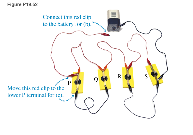
52. Figure P19.52 shows a real circuit that consists of four identical lightbulbs that are
mounted in yellow holders (each lightbulb holder has two terminals) and a battery. (a)
Draw a diagram for this circuit. (b) Predict which lightbulb(s) will glow if you connect the
free red alligator clip to the free terminal of the battery. (c) Now move the far left red
alligator clip from the upper to the lower terminal of the bulb P (as explained on the
figure). Draw a new circuit diagram and predict which lightbulb(s) now glows.
Figure P19.52
Connect this red clip
to the battery for (b).*
Move this red clip to the
lower P terminal for (c).
P
R
S
Essential University Physics: Volume 2 (3rd Edition)
Knowledge Booster
Learn more about
Need a deep-dive on the concept behind this application? Look no further. Learn more about this topic, physics and related others by exploring similar questions and additional content below.
How To Solve Any Resistors In Series and Parallel Combination Circuit Problems in Physics; Author: The Organic Chemistry Tutor;https://www.youtube.com/watch?v=eFlJy0cPbsY;License: Standard YouTube License, CC-BY


 Principles of Physics: A Calculus-Based TextPhysicsISBN:9781133104261Author:Raymond A. Serway, John W. JewettPublisher:Cengage Learning
 Physics for Scientists and Engineers, Technology ...PhysicsISBN:9781305116399Author:Raymond A. Serway, John W. JewettPublisher:Cengage Learning
 College PhysicsPhysicsISBN:9781938168000Author:Paul Peter Urone, Roger HinrichsPublisher:OpenStax College
 Physics for Scientists and Engineers with Modern ...PhysicsISBN:9781337553292Author:Raymond A. Serway, John W. JewettPublisher:Cengage Learning
 Physics for Scientists and EngineersPhysicsISBN:9781337553278Author:Raymond A. Serway, John W. JewettPublisher:Cengage Learning