Problem 1RQ: Review Question 19.1 What condition(s) is/are needed for electric charge to continuously travel from... Problem 2RQ: Review Question 19.2 Describe the changes in electric potential through a circuit and relate them to... Problem 3RQ: Review Question 19.3 Explain the meaning of the term a complete circuit." Problem 4RQ: Review Question 19.4 Why does it make sense that all ammeters in Figure 19.16 have the same reading? Problem 5RQ: Review Question 19.5 What experimental evidence supports the hypothesis that in your house the... Problem 6RQ: Review Question 19.6 Eugenia says that the power of an electric device is directly proportional to... Problem 7RQ: Review Question 19.7 Where is the electric potential higher: where the current enters" a resistor or... Problem 8RQ: Review Question 19.8 Rank the four identical bulbs shown in Figure 19.33 from brightest to dimmest.... Problem 9RQ: Review Question 19.9 What does it mean when you get a negative value for the current in the circuit... Problem 10RQ: Review Question 19.10 Why does the resistance of a lightbulb increase as the current through it... Problem 1MCQ: Two identical bulbs are connected on parallel across the battery shown in Figure Q19.1. There is an... Problem 2MCQ: Compare the potential difference across bulbs 1 and 2 in Figure Q19.1 after the switch is closed.... Problem 3MCQ: Two identical bulbs are in series as shown in Figure Q19.3. Which statement is correct? a. The... Problem 4MCQ: 4. Which statement below about the potential difference across the battery and across the identical... Problem 5MCQ: Three circuits with identical bulbs and emf sources are shown in Figure Q19.5. Rank the circuits in... Problem 6MCQ: 6. Rank in order the potential differences across each of the five bulbs in the three circuits in... Problem 7MCQ: 7. Rank in order the five identical bulbs in the circuit shown in Figure Q19.7, listing the... Problem 8MCQ: Four identical bulbs are shown in the circuit in Figure Q19.8. With the switch open, bulbs 1, 2, and... Problem 9MCQ: Four identical bulbs are shown in the circuit in Figure Q19.9 with the switch open. How does the... Problem 10MCQ: Consider the circuit in Figure Q19.10. The switch is open. What is the potential difference across... Problem 11MCQ: 11. Figure Q19.1 shows graphs for an incandescent lightbulb and a resistor. Choose all correct... Problem 12MCQ: If an electric current were due to electrons moving only on the surface of a wire rather than... Problem 13MCQ: 13. Three light sources (a lightbulb, a blue LED are connected with two resistors and a 3.0-V... Problem 15CQ: What is the role of a battery in an electric circuit? Describe a mechanical analogy. Problem 16CQ: 16. Compare and contrast the physical quantities emf and potential difference.
Problem 17CQ: Birds on high power lines Why can birds perch on a 100,000-V power line with no adverse effects? Problem 18CQ: 18. Preventing electric shock When a person is repairing electrical equipment and can encounter high... Problem 19CQ: (a) Using a voltmeter, how can you determine the electric current through a resistor? (b) Using an... Problem 20CQ: (a) What does it mean if the current through a resistor is 3 A? (b) What does it mean if the... Problem 21CQ: 21. Resistors become warm when there is an electric current through them. Why doesn't this... Problem 22CQ: At one time aluminum rather than copper wires were used to carry electric current through homes.... Problem 23CQ: 23. How do you connect an ammeter in a circuit to measure the current? How do you connect a... Problem 24CQ: Why do we connect electric devices in a home in parallel rather than in series? Problem 26CQ: 26. Construct an electric circuit that is analogous to your circulatory system. Indicate the... Problem 27CQ: 27. Most Christmas tree lights with incandescent bulbs are connected in parallel (a) Describe one... Problem 28CQ: 28. Two students are arguing. Student A says that Ohm's law is only valid for ohmic resistors.... Problem 29CQ: Use the laws of energy and charge conservation to explain Kirchhoffs rules. Problem 30CQ: When you close the switch in the circuit in Figure Q19.30, the capacitor charges. When you open the... Problem 1P: 1. A bulb in a table lamp has a current of 0.50 A through it. Determine two physical quantities... Problem 2P: A long wire is connected to the terminals of a battery. In 8.0 s, 9.61020 electrons pass a cross... Problem 3P: A typical flashlight battery will produce a 0.50-A current for about 3h before losing its charge.... Problem 4P: 4. * Four friends each have a battery, a bulb, and one wire. They use the materials to try to light... Problem 5P: 5. Draw a circuit that has a battery, a lightbulb, and connecting wires Draw a schematic of a water... Problem 6P: Add another battery to the circuit described in Problem 19.5. In how many different ways can you do... Problem 7P: Add another lightbulb to the circuit with one battery described in Problem 19.5. In how many... Problem 8P: A 9.0-V battery is connected to a resistor so that there is a 0.50-A current through the resistor.... Problem 10P: 10. * A graph of the electric potential versus location in a series circuit with 1.0 A of current is... Problem 11P: 11. Sketch a potential-versus-location graph for the circuit shown in Figure P19.11 . Start at A and... Problem 12P: 12. Bio Electric currents in the body A person accidentally touches a 120-V electric line with one... Problem 13P: 13. An automobile lightbulb has a 1.0-A current when it is connected to a 12-V battery. What can you... Problem 14P: * If a long wire is connected to the terminals of a 12-V battery, 6.41019 electrons pass a cross... Problem 15P: Determine the current through a 2.5- resistor when connected across two 1.5-V batteries in series (a... Problem 16P: 16. * You have a circuit with a 50-Ω, a 100- Ω, and a 150- Ω resistor, and a battery connected in... Problem 17P: You have a circuit with a 50-, a 100- , and a 150- resistor connected in parallel to the same... Problem 18P: 18. * A toy has two red LEDs (), two green LEDs (), and two blue LEDs () connected in series. (a)... Problem 19P: * You want to power a green LED (VOpenG=2.1V) and a red LED (VOpenR=1.6V) using a 9.0-V battery You... Problem 20P: 20. * A circuit consists of a green LED and a resistor connected in series with a variable power... Problem 21P: 21. * You connect a 50-Ω resistor to a 9-V battery whose internal resistance is 1 Ω. (a) Determine... Problem 22P: 22. * EST Making tea You use an electric teapot to make tea It takes about 2 min to boll 0.5 L of... Problem 23P: * If a long wire is connected to the terminals of a 12-V battery, 6.41019 electrons pass a cross... Problem 24P: ** Three friends are arguing with each other. Adam says that a battery will send the same current to... Problem 25P: 25. * You have a 40-W lightbulb and a 100-W bulb. What do these readings mean? Can we say that the... Problem 26P: * Does a 60-W lightbulb have more or less resistance than a 100-W bulb? Explain. Problem 27P: 27. * (a) Write two loop rule equations and one junction rule equation for the circuit in Figure... Problem 28P: 28. * (a) Write Kirchhoff's loop rule for the circuit shown in Figure P19.28 for the case in which ... Problem 29P: 29. * Repeat parts (a) and (b) of the previous problem for the case in which (c) Determine the... Problem 30P: * (a) Determine the value of 1 so that there is a clockwise current of 1.0 A in the circuit shown in... Problem 31P: 31. ** The current through resistor in Figure P19.27 is 2.0 A Determine the currents through... Problem 32P: andR3 shown in Figure P19.27 satisfy the relation I2/I3=R3/R2. Problem 33P: 33. * (a) Write the loop rule for two different loops in the circuit shown in Figure P19.33 and the... Problem 34P: 34. ** Determine the value of , shown in Figure P19.33 so that the current through equals twice... Problem 35P: * Determine (a) the equivalent resistance of resistors R1,R2,andR3 in Figure P19.35 for R1=28,... Problem 36P: 36. (a) Determine the equivalent resistance of resistors and in Figure P19.35 for , and . (b)... Problem 37P: 37. * Determine the equivalent resistance of the resistors shown in Figure P19.37 if and
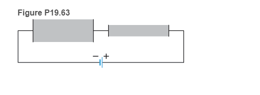
Problem 38P: * Determine (a) the equivalent resistance of the resistors in the circuit in Figure P19.38 and (b)... Problem 40P: You close the switch in the circuit in Figure P19.40 and wait until the currents stop changing. (a)... Problem 41P: * You close the switch in the circuit in Figure P19.41 and wait until the currents stop changing.... Problem 42P: 42. * Home wiring A simplified electrical circuit for a home is shown in Figure P19.42 . (a)... Problem 43P: 43. ** (a) Write Kirchhoff's rules for two loops and one junction in the circuit shown in Figure... Problem 44P: of internal resistance. Because each row has the same emf and the rows are connected together on... Problem 45P: 45. Home wiring A 120-V electrical line m a home is connected to a 60-W lightbulb, a 180-W... Problem 46P: * Tree lights Nine tree lights are connected m parallel across a 120-V potential difference. The... Problem 47P: 47. * Two lightbulbs use 30 W and 60 W, respectively, when connected in parallel to a 120-V source.... Problem 48P: * Three identical resistors, when connected in series, transform electrical energy into thermal... Problem 49P: . (a) Determine the power delivered to a resistor R connected to the battery terminals for values of... Problem 50P: * Determine the equivalent resistance of the circuit in Figure P19.50 when (a) both switches are... Problem 51P: 51 toI4 from largest to smallest Assume all wires have negligible resistance and the battery has... Problem 52P: Figure P19.52 shows a real circuit that consists of four identical lightbulbs that are mounted in... Problem 53P: * A 100-m-long copper wire of radius 0.12 mm and mass 40 g is connected across a 1.5-V battery. Make... Problem 54P: 54. * BMT subway rail resistance The BMT subway line in New York City stretches roughly 30 km from... Problem 55P: * Thermometer A platinum resistance thermometer consists of a 0.10-mm-diameter platinum wire wrapped... Problem 56P: As the potential difference in volts across a thin platinum wire increases, the current in amperes... Problem 57P: 57. * BIO Respiration detector A respiration detector monitors a person's breathing. One type... Problem 58P: * A wire whose resistance is R is stretched so that its length is tripled while its volume remains... Problem 59P: 59. * Ratio reasoning Determine the ratio of the resistances of two wires that are identical except... Problem 60P: ** Electronics detective You need to determine the mass and length of the wire inside a particular... Problem 61P: 61. * A battery produces a 2.0-A current when connected to an unknown resistor of resistance R. When... Problem 62P: 62. * Resistance of human nerve cell Some human nerve cells have a long, thin cylindrical cable (the... Problem 63P: 63. * Conductive textiles Metal strands can be woven into textiles to make them conductive You have... Problem 64GP: 64. * EST Figure P19.64 shows an I-versus-V graph for an incandescent lightbulb and a resistor... Problem 65GP: * EST Figure P19.64 shows an I-versus- V graph for an incandescent lightbulb and a resistor (data... Problem 66GP: *EST Figure P19.64 shows an I-versus- V graph for an incandescent lightbulb and a resistor (data are... Problem 67GP: * Wiring high-fidelity speakers Your high-fidelity amplifier has one output for a speaker of... Problem 68GP: 68 * BIO EST Lifting forearm by electric current You are asked to evaluate an idea for making it... Problem 69GP: 69. * EST Switches You have a power supply, a 10-W bulb, and a 15-W bulb. You also have two types of... Problem 70GP: ** Wiring a staircase Devise an electric circuit that will allow you to turn a stairway lightbulb on... Problem 72GP: 72. ** EST Electric water heater An electric hot water heater has a 7000-W resistive heating... Problem 73GP: 73. ** BIO EST The hands and arms as a conductor While doing laundry you reach to turn on the light... Problem 75GP: 75. * A nickel wire of length L and a voltmeter are connected to a battery as shown in Figure... Problem 76GP: ** Solve the previous problem if the internal resistance of the battery is r and the resistance of... Problem 77GP: * EST Figure P19.77 shows an | I | -versus-V graph of a circuit that consists of a red LED... Problem 78GP: VI a. Connect a voltmeter to a batterys terminals. Record the voltage reading V Then (in a different... Problem 79GP: equaled the number of electrons passing a cross section in a wire when there is a 1.0-A current... Problem 80GP: 80. * A 5.0-A current caused by moving electrons flows through a wire. (a) Determine the number of... Problem 81GP: 81. ** BIO Current across membrane wall of axon An axon cable that connects the input and output... Problem 82RPP: BIO Signals in nerve cells stimulate muscles The input end of a human nerve cell is connected to an... Problem 83RPP: BIO Signals in nerve cells stimulate muscles The input end of a human nerve cell is connected to an... Problem 84RPP: BIO Signals in nerve cells stimulate muscles The input end of a human nerve cell is connected to an... Problem 85RPP: BIO Signals in nerve cells stimulate muscles The input end of a human nerve cell is connected to an... Problem 86RPP: 86. The horizontal 4-Ω resistors in the two circuits in Figure P19.86 represent the resistance of a... Problem 87RPP: 87. Suppose nerve impulses travel at 100 m/s in the axons of nerve cells from your fingers to your... Problem 88RPP: BIO Effect of electric current on human body Nerve impulses are initiated at the input end of a... Problem 89RPP: BIO Effect of electric current on human body Nerve impulses are initiated at the input end of a... Problem 90RPP: BIO Effect of electric current on human body Nerve impulses are initiated at the input end of a... Problem 91RPP: BIO Effect of electric current on human body Nerve impulses are initiated at the input end of a... Problem 92RPP: BIO Effect of electric current on human body Nerve impulses are initiated at the input end of a... Problem 93RPP: BIO Effect of electric current on human body Nerve impulses are initiated at the input end of a... Problem 94RPP: BIO Effect of electric current on human body Nerve impulses are initiated at the input end of a... format_list_bulleted


 College PhysicsPhysicsISBN:9781938168000Author:Paul Peter Urone, Roger HinrichsPublisher:OpenStax College
 Principles of Physics: A Calculus-Based TextPhysicsISBN:9781133104261Author:Raymond A. Serway, John W. JewettPublisher:Cengage Learning
 Physics for Scientists and EngineersPhysicsISBN:9781337553278Author:Raymond A. Serway, John W. JewettPublisher:Cengage Learning
 Physics for Scientists and Engineers with Modern ...PhysicsISBN:9781337553292Author:Raymond A. Serway, John W. JewettPublisher:Cengage Learning
 College PhysicsPhysicsISBN:9781305952300Author:Raymond A. Serway, Chris VuillePublisher:Cengage Learning