
Statics and Mechanics of Materials (5th Edition)
5th Edition
ISBN: 9780134382593
Author: Russell C. Hibbeler
Publisher: PEARSON
expand_more
expand_more
format_list_bulleted
Concept explainers
Videos
Textbook Question
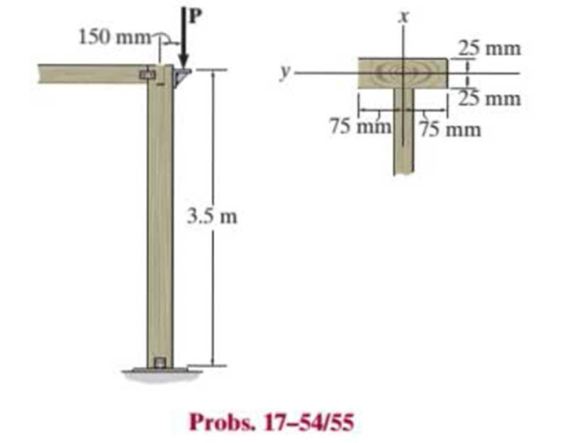
Chapter 17.4, Problem 55P
The wood column is pinned at its base and top. Determine the maximum eccentric force P the column can support without causing it to either buckle or yield. Take E = 10 GPa and σY = 15 MPa.
Expert Solution & Answer
Want to see the full answer?
Check out a sample textbook solution
Students have asked these similar questions
5. (计算题)
Calculate the DOF of following mechanisms. If there are compound hinge, passive DOF or Redundant Constraint, please point
them out.
品
⑤A
(a) 凸轮拨杆机构
6.(计算题)
Calculate the DOF of following mechanisms. If there are compound hinge, passive DOF or Redundant Constraint, please point
them out.
E
D
A
B
C
F
A hot surface at 150°C is to be cooled by attaching 3-cm-long, 0.25-cm-diameter aluminum pin fins (k = 237 W/m-K) to it, with a center-
to-center distance of 0.6 cm. The temperature of the surrounding medium is 30°C, and the heat transfer coefficient on the surfaces is
35 W/m²K. Determine the rate of heat transfer from the surface for a 1-m × 1-m section of the plate. Also determine the overall
effectiveness of the fins.
0.6 cm
0.25 cm
The total rate of heat transfer is
kW.
The fin effectiveness is
Chapter 17 Solutions
Statics and Mechanics of Materials (5th Edition)
Ch. 17.3 - A 50-in.-long steel rod has a diameter of 1 in....Ch. 17.3 - A 12-ft wooden rectangular column has the...Ch. 17.3 - Prob. 3FPCh. 17.3 - A steel pipe is fixed supported at its ends. If it...Ch. 17.3 - Determine the maximum force P that can be...Ch. 17.3 - The A992 steel rod BC has a diameter of 50 mm and...Ch. 17.3 - Determine the critical buckling load for the...Ch. 17.3 - Prob. 2PCh. 17.3 - The aircraft link is made from an A992 steel rod....Ch. 17.3 - Rigid bars AB and BC are pin connected at B. If...
Ch. 17.3 - A 2014-T6 aluminum alloy column has a length of 6...Ch. 17.3 - Prob. 6PCh. 17.3 - Prob. 7PCh. 17.3 - Prob. 8PCh. 17.3 - A steel column has a length of 9 m and is fixed at...Ch. 17.3 - A steel column has a length of 9 m and is pinned...Ch. 17.3 - The A992 steel angle has a cross-sectional area of...Ch. 17.3 - The 50-mm-diameter C86100 bronze rod is fixed...Ch. 17.3 - Determine the maximum load P the frame can support...Ch. 17.3 - Prob. 14PCh. 17.3 - Prob. 15PCh. 17.3 - An A992 steel W200 46 column of length 9 m is...Ch. 17.3 - Prob. 17PCh. 17.3 - Prob. 18PCh. 17.3 - Prob. 19PCh. 17.3 - Prob. 20PCh. 17.3 - Prob. 21PCh. 17.3 - The deck is supported by the two 40-mm-square...Ch. 17.3 - Prob. 23PCh. 17.3 - Prob. 24PCh. 17.3 - Prob. 25PCh. 17.3 - Prob. 26PCh. 17.3 - Prob. 27PCh. 17.3 - The linkage is made using two A992 steel rods,...Ch. 17.3 - The linkage is made using two A-36 steel rods,...Ch. 17.3 - The linkage is made using two A-36 steel rods,...Ch. 17.3 - The steel bar AB has a rectangular cross section....Ch. 17.3 - Determine if the frame can support a load of P =...Ch. 17.3 - Determine the maximum allowable load P that can be...Ch. 17.3 - Prob. 34PCh. 17.3 - Prob. 35PCh. 17.3 - The members of the truss are assumed to be pin...Ch. 17.3 - The members of the truss are assumed to be pin...Ch. 17.3 - The truss is made from A992 steel bars, each of...Ch. 17.3 - The truss is made from A992 steel bars, each of...Ch. 17.3 - The steel bar AB of the frame is assumed to be pin...Ch. 17.3 - Prob. 41PCh. 17.3 - Prob. 42PCh. 17.3 - Prob. 43PCh. 17.3 - Prob. 44PCh. 17.3 - Consider an ideal column as in Fig. 1710d, having...Ch. 17.4 - Prob. 46PCh. 17.4 - Prob. 47PCh. 17.4 - The W10 12 structural A-36 steel column is used...Ch. 17.4 - The aluminum column is fixed at the bottom and...Ch. 17.4 - Prob. 50PCh. 17.4 - The aluminum rod is fixed at its base and free and...Ch. 17.4 - Prob. 52PCh. 17.4 - Prob. 53PCh. 17.4 - Prob. 54PCh. 17.4 - The wood column is pinned at its base and top....Ch. 17.4 - Prob. 56PCh. 17.4 - Prob. 57PCh. 17.4 - Prob. 58PCh. 17.4 - Prob. 59PCh. 17.4 - Prob. 60PCh. 17.4 - Prob. 61PCh. 17.4 - Prob. 62PCh. 17.4 - The W14 53 column is fixed at its base and free...Ch. 17.4 - Prob. 64PCh. 17 - The wood column is 4 m long and is required to...Ch. 17 - Prob. 2RPCh. 17 - A steel column has a length of 5 m and is free at...Ch. 17 - Prob. 4RPCh. 17 - Prob. 5RPCh. 17 - If P = 15 kip, determine the required minimum...Ch. 17 - Prob. 7RPCh. 17 - The W200 46 wide-flange A992-steel column can be...Ch. 17 - The wide-flange A992 steel column has the cross...Ch. 17 - The wide-flange A992 steel column has the cross...
Knowledge Booster


Learn more about
Need a deep-dive on the concept behind this application? Look no further. Learn more about this topic, mechanical-engineering and related others by exploring similar questions and additional content below.Similar questions
- Consider a stainless steel spoon (k = 8.7 Btu/h·ft·°F) partially immersed in boiling water at 200°F in a kitchen at 75°F. The handle of the spoon has a cross section of 0.08 in × 0.5 in and extends 7 in in the air from the free surface of the water. The heat transfer coefficient at the exposed surfaces of the spoon handle is 3 Btu/h·ft2·°F. NOTE: This is a multi-part question. Once an answer is submitted, you will be unable to return to this part. A spoon is placed inside the container, such that the distance of the water level from the top end of the handle of the spoon is 7 meters. T sub air is indicated in the region outside the container. Identify the assumptions required to solve the problem. Check All That Apply One-dimensional heat transfer analysis is used to solve the problem. One-dimensional heat transfer analysis is used to solve the problem. Bi-dimensional heat transfer analysis is used to solve the problem. Bi-dimensional heat transfer analysis is…arrow_forwardA turbine blade made of a metal alloy (k=17 W/m-K) has a length of 5.3 cm, a perimeter of 11 cm, and a cross-sectional area of 5.13 cm². The turbine blade is exposed to hot gas from the combustion chamber at 1133°C with a convection heat transfer coefficient of 538 W/m²K. The base of the turbine blade maintains a constant temperature of 450°C and the tip is adiabatic. NOTE: This is a multi-part question. Once an answer is submitted, you will be unable to return to this part. Hot gas h=538 W/m²K -Turbine blade k = 17 W/m-K p=11 cm, L=5.3 cm A = 5.13 cm² -T=450°C Determine the heat transfer rate to the turbine blade. W. The heat transfer rate isarrow_forwardConsider a very long, slender rod. One end of the rod is attached to a base surface maintained at Tb, while the surface of the rod is exposed to an air temperature of 400°C. Thermocouples imbedded in the rod at locations 25 mm and 120 mm from the base surface register temperatures of 325°C and 375°C, respectively. NOTE: This is a multi-part question. Once an answer is submitted, you will be unable to return to this part. . x1 32 x Calculate the rod base temperature (°C). The rod base temperature is °C. Air T∞arrow_forward
- A rotating shaft of 20 mm diameter is simply supported. The shaft is loaded with a transverse load of 10 kN as shown in the figure. The shaft is made from AISI 1095 hot-rolled steel. The surface has been machined. The shaft operate at temperature T = 450 °C. Consider a reliability factor of 95%. Determine (a) Calculate the reaction forces R, and R₂ (2 points) (b) Draw the shear force and bending moment diagrams and determine the maximum bending moment and shear force. (6 points) 200 mm 20 mm 10,000 N -50 mm- A Not to scale. (c) Determine the critical location of the shaft and the maximum effective stresses. (3 points) (d) Calculate the safety factor against yielding. Does the shaft undergo local yielding? (2 points) (e) Determined the endurance limit, adjusted as necessary with Marin factors. (12 points) (f) Calculate the fatigue factor of safety based on achieving infinite life. (2 points) (g) If the fatigue factor of safety is less than 1 (hint: it should be for this problem), then…arrow_forward(read image)arrow_forward(read image)arrow_forward
- 6: Refer to the figure.Given: W1 = 200 kN/m; W2 = 300 kN/m; L1 = 2 m; L2 = 3 m; L3 = 2 m(a) Calculate the total length L so that the resulting upward pressureq is uniform. (b) draw the shear and moment diagram and determinethe maximum shear, maximum positive and negative bendingmoments.arrow_forwardA six cylinder, four-stroke diesel engine develops a power of 200 kW at 2000 rpm. The bsfc is 0.2 kW/kg h of fuel with 34.9° API. The fuel is injected at an average pressure of 350 bar and the pressure in the combustion chamber is 40 bar. Assuming Ca for injector 0.75 and the atmospheric pressure 1 bar. Determine the period of injection in seconds if the total orifice area required per injector is 0.4876 × 10⁻⁶ m².arrow_forwardTrieed a detailed drawing Win explanatio LL Antsmi 1981x pu + 96252 اه 6. The Pre-combustion chamber design engines employ nozzle type commonly referred to as a ....... a. inward-opening nozzle b. multiple-hole nozzle. c. pintle nozzle. d. none of these. 7. If the temperature of the spark plug tip is less than 350 °C, ......... a. the plug might not work. b. the carbon deposits would increase. 8. Port injection sprays fuel....... c. pre-ignition will occur. d. none of these. a. towards the intake valve. b. in the engine cylinder. c. in the throttle body assembly. d. none of these. 9. When the fuel-air mixture changed from best power to a richer ratio, the spark advance should be........ a. increased. b. decreased. c. left unchanged. d. none of these. d. none of these. 10. Spark plugs are classified as hot plugs and cold plugs depending upon ........ a. spark gap. b. the type of plug c. the operating temperature insulator. range of the electrode tip. ---20125 750 x2.01 SP 5.arrow_forward
arrow_back_ios
SEE MORE QUESTIONS
arrow_forward_ios
Recommended textbooks for you
 Elements Of ElectromagneticsMechanical EngineeringISBN:9780190698614Author:Sadiku, Matthew N. O.Publisher:Oxford University Press
 Mechanics of Materials (10th Edition)Mechanical EngineeringISBN:9780134319650Author:Russell C. HibbelerPublisher:PEARSON
 Thermodynamics: An Engineering ApproachMechanical EngineeringISBN:9781259822674Author:Yunus A. Cengel Dr., Michael A. BolesPublisher:McGraw-Hill Education
 Control Systems EngineeringMechanical EngineeringISBN:9781118170519Author:Norman S. NisePublisher:WILEY
 Mechanics of Materials (MindTap Course List)Mechanical EngineeringISBN:9781337093347Author:Barry J. Goodno, James M. GerePublisher:Cengage Learning
 Engineering Mechanics: StaticsMechanical EngineeringISBN:9781118807330Author:James L. Meriam, L. G. Kraige, J. N. BoltonPublisher:WILEY
Elements Of Electromagnetics
Mechanical Engineering
ISBN:9780190698614
Author:Sadiku, Matthew N. O.
Publisher:Oxford University Press
Mechanics of Materials (10th Edition)
Mechanical Engineering
ISBN:9780134319650
Author:Russell C. Hibbeler
Publisher:PEARSON
Thermodynamics: An Engineering Approach
Mechanical Engineering
ISBN:9781259822674
Author:Yunus A. Cengel Dr., Michael A. Boles
Publisher:McGraw-Hill Education
Control Systems Engineering
Mechanical Engineering
ISBN:9781118170519
Author:Norman S. Nise
Publisher:WILEY
Mechanics of Materials (MindTap Course List)
Mechanical Engineering
ISBN:9781337093347
Author:Barry J. Goodno, James M. Gere
Publisher:Cengage Learning
Engineering Mechanics: Statics
Mechanical Engineering
ISBN:9781118807330
Author:James L. Meriam, L. G. Kraige, J. N. Bolton
Publisher:WILEY
Column buckling; Author: Amber Book;https://www.youtube.com/watch?v=AvvaCi_Nn94;License: Standard Youtube License