
Statics and Mechanics of Materials (5th Edition)
5th Edition
ISBN: 9780134382593
Author: Russell C. Hibbeler
Publisher: PEARSON
expand_more
expand_more
format_list_bulleted
Concept explainers
Videos
Textbook Question
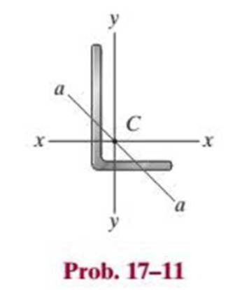
Chapter 17.3, Problem 11P
The A992 steel angle has a cross-sectional area of A = 2.48 in2 and a radius of gyration about the x axis of rx = 1.26 in. and about the y axis of ry = 0.879 in. The smallest radius of gyration occurs about the a–a axis and is ra = 0.644 in. If the angle is to be used as a pin-connected 10-ft-long column, determine the largest axial load that can be applied through its centroid C without causing it to buckle.
Expert Solution & Answer
Want to see the full answer?
Check out a sample textbook solution
Students have asked these similar questions
The A992 steel angle has a cross-sectional area of A = 2.48 in2 and a radius of gyration about the x axis of rx = 1.26 in. and about the y axis of ry = 0.879 in. The smallest radius of gyration occurs about the a–a axis and is ra = 0.644 in. If the angle is to be used as a pin-connected 10-ft-long column, determine the largest axial load that can be applied through its centroid C without causing it to buckle.
Determine the vertical displacement of point B. Each A-36 steel member has a cross-
sectional area of 400 mm². Using Castigliano's Theorem.
30 kN
-1.5 m-
B
20 kN
-1.5 m
Figure 1
2m
The wires each have a diameter of 1 2 in., length of 2 ft, and are made from 304 stainless steel. If P = 6 kip, determine the angle of tilt of the rigid beam AB.
Chapter 17 Solutions
Statics and Mechanics of Materials (5th Edition)
Ch. 17.3 - A 50-in.-long steel rod has a diameter of 1 in....Ch. 17.3 - A 12-ft wooden rectangular column has the...Ch. 17.3 - Prob. 3FPCh. 17.3 - A steel pipe is fixed supported at its ends. If it...Ch. 17.3 - Determine the maximum force P that can be...Ch. 17.3 - The A992 steel rod BC has a diameter of 50 mm and...Ch. 17.3 - Determine the critical buckling load for the...Ch. 17.3 - Prob. 2PCh. 17.3 - The aircraft link is made from an A992 steel rod....Ch. 17.3 - Rigid bars AB and BC are pin connected at B. If...
Ch. 17.3 - A 2014-T6 aluminum alloy column has a length of 6...Ch. 17.3 - Prob. 6PCh. 17.3 - Prob. 7PCh. 17.3 - Prob. 8PCh. 17.3 - A steel column has a length of 9 m and is fixed at...Ch. 17.3 - A steel column has a length of 9 m and is pinned...Ch. 17.3 - The A992 steel angle has a cross-sectional area of...Ch. 17.3 - The 50-mm-diameter C86100 bronze rod is fixed...Ch. 17.3 - Determine the maximum load P the frame can support...Ch. 17.3 - Prob. 14PCh. 17.3 - Prob. 15PCh. 17.3 - An A992 steel W200 46 column of length 9 m is...Ch. 17.3 - Prob. 17PCh. 17.3 - Prob. 18PCh. 17.3 - Prob. 19PCh. 17.3 - Prob. 20PCh. 17.3 - Prob. 21PCh. 17.3 - The deck is supported by the two 40-mm-square...Ch. 17.3 - Prob. 23PCh. 17.3 - Prob. 24PCh. 17.3 - Prob. 25PCh. 17.3 - Prob. 26PCh. 17.3 - Prob. 27PCh. 17.3 - The linkage is made using two A992 steel rods,...Ch. 17.3 - The linkage is made using two A-36 steel rods,...Ch. 17.3 - The linkage is made using two A-36 steel rods,...Ch. 17.3 - The steel bar AB has a rectangular cross section....Ch. 17.3 - Determine if the frame can support a load of P =...Ch. 17.3 - Determine the maximum allowable load P that can be...Ch. 17.3 - Prob. 34PCh. 17.3 - Prob. 35PCh. 17.3 - The members of the truss are assumed to be pin...Ch. 17.3 - The members of the truss are assumed to be pin...Ch. 17.3 - The truss is made from A992 steel bars, each of...Ch. 17.3 - The truss is made from A992 steel bars, each of...Ch. 17.3 - The steel bar AB of the frame is assumed to be pin...Ch. 17.3 - Prob. 41PCh. 17.3 - Prob. 42PCh. 17.3 - Prob. 43PCh. 17.3 - Prob. 44PCh. 17.3 - Consider an ideal column as in Fig. 1710d, having...Ch. 17.4 - Prob. 46PCh. 17.4 - Prob. 47PCh. 17.4 - The W10 12 structural A-36 steel column is used...Ch. 17.4 - The aluminum column is fixed at the bottom and...Ch. 17.4 - Prob. 50PCh. 17.4 - The aluminum rod is fixed at its base and free and...Ch. 17.4 - Prob. 52PCh. 17.4 - Prob. 53PCh. 17.4 - Prob. 54PCh. 17.4 - The wood column is pinned at its base and top....Ch. 17.4 - Prob. 56PCh. 17.4 - Prob. 57PCh. 17.4 - Prob. 58PCh. 17.4 - Prob. 59PCh. 17.4 - Prob. 60PCh. 17.4 - Prob. 61PCh. 17.4 - Prob. 62PCh. 17.4 - The W14 53 column is fixed at its base and free...Ch. 17.4 - Prob. 64PCh. 17 - The wood column is 4 m long and is required to...Ch. 17 - Prob. 2RPCh. 17 - A steel column has a length of 5 m and is free at...Ch. 17 - Prob. 4RPCh. 17 - Prob. 5RPCh. 17 - If P = 15 kip, determine the required minimum...Ch. 17 - Prob. 7RPCh. 17 - The W200 46 wide-flange A992-steel column can be...Ch. 17 - The wide-flange A992 steel column has the cross...Ch. 17 - The wide-flange A992 steel column has the cross...
Knowledge Booster


Learn more about
Need a deep-dive on the concept behind this application? Look no further. Learn more about this topic, mechanical-engineering and related others by exploring similar questions and additional content below.Similar questions
- Question 17 A wide flange section has the following properties: bf = 200 mm tf = 8 mm d = 300 mm tw = 11 mm Calculate the radius of gyration in mm about the y-axis.arrow_forward8-26 to 8–31 For each built-up section shown in Figs. P8–26 to P8–31, determine the moment of inertia and the radius of gyration of the section with respect te the horizontal centroidal axis. +12 in. X 1 in. plate 300 mm X 20 mm plate W14 X 61 C250 × 0.438 100 mm 300 mm X 20 mm plate -12 in. X1 in. plate FIGURE P8-26 FIGURE P8-27arrow_forwardProblem 2. The assembly consists of three titanium (Ti- 6A1-4V) rods and a rigid bar AC. The cross-sectional area of each rod is given in the figure. If a force of 6 kip is applied to the ring F, determine the horizontal displacement of point F, and determine the angle of tilt of rigid bar AC. B D 4 ft ACD = 1 in² AAB 6 ft 1.5 in² E 2 ft 1 ft 1 ft AEF = 2 in² 6 kiparrow_forward
- The wing spar ABD of a light plane is made from 2014-T6 aluminum and has a cross- sectional area of 800 mm², a height of 79 mm, and a moment of inertia about its neutral axis of 1.07(106) mª. Assume A, B, and C' are pins. The neutral axis passes through the cross-section at half of its height. Connection is made along the central longitudinal axis of the spar. The anticipated loading is to be as shown. (Figure 1) Determine the absolute maximum bending stress in the spar. 0.6 m 14.4 kN/m 0.9 m B -1.8 m-arrow_forwardA channel and a plate are welded together as shown to form a section that is symmetrical with respect to the y axis. Determine the moments of inertia of the combined section with respect to its centroidal x and yaxes if a = 14 in. 0.5 in. y C a CS×115 The moment of inertia with respect to the x axis is The moment of inertia with respect to the yaxis is in4 in4 Karrow_forwardDetermine the radius of gyration kx (in inches) of the homogeneous body (shown in the image below) about the x axis. The specific weight of the material is g = 400 Ib/ft°, the length /= 10 in., and the exponent in the equation a = 1.9. Please pay attention: the numbers may change since they are randomized. Your answer must include 3 places after the decimal point. ya = x Your Answer: Answerarrow_forward
- The rigid bar BC is supported by the steel rod AC of cross-sectional area 0.31 in2. Find the vertical displacement (in inches and absolute value) of point Coaused by the 2888-lb load if x = 8.7 ft and 8 = 46.5-. Use E = 29159 ksi for steel. Note: Round off the final answer to four decimal places. Rigid B Parrow_forwardQuestion 1: Given that Tuitow = 50 MPa for the rod AB and tattow = 25 MPa for the rod BC. If T=1250 N.m, find the required radius for both rods. Ahmtmum AB = BC =arrow_forwardVerify that the radius of gyration for a circle of diameter d with respect to a centroidal axis is r = d/ 4. 8-2arrow_forward
- 5. Two C310x45 channels are latticed together so they have equal moments of inertia about the principal axes. Determine the minimum length of column having this section, assuming pinned ends, E = 200 GPa, and a proportional limit of 240 MPa. What safe load will the column carry for the length of 12 m with a factor of safety of 2.5? For C310x45, take I = 67.3x10⁻⁶ m4 %3D Ans L = 9.89 m, F = 738 kNarrow_forwardThe cross section of a bearing block is shown in the figure by the shaded area. Calculate the moment of inertia of the section about its base a-a. Assume b = 14 in., h = 3 in., r= 2 in, R = 4 in. R h a Answer: Io-a - i in.4 Save for Later Attempts: 0 of 1 used Submit Answerarrow_forwardASAParrow_forward
arrow_back_ios
SEE MORE QUESTIONS
arrow_forward_ios
Recommended textbooks for you
 Elements Of ElectromagneticsMechanical EngineeringISBN:9780190698614Author:Sadiku, Matthew N. O.Publisher:Oxford University Press
 Mechanics of Materials (10th Edition)Mechanical EngineeringISBN:9780134319650Author:Russell C. HibbelerPublisher:PEARSON
 Thermodynamics: An Engineering ApproachMechanical EngineeringISBN:9781259822674Author:Yunus A. Cengel Dr., Michael A. BolesPublisher:McGraw-Hill Education
 Control Systems EngineeringMechanical EngineeringISBN:9781118170519Author:Norman S. NisePublisher:WILEY
 Mechanics of Materials (MindTap Course List)Mechanical EngineeringISBN:9781337093347Author:Barry J. Goodno, James M. GerePublisher:Cengage Learning
 Engineering Mechanics: StaticsMechanical EngineeringISBN:9781118807330Author:James L. Meriam, L. G. Kraige, J. N. BoltonPublisher:WILEY
Elements Of Electromagnetics
Mechanical Engineering
ISBN:9780190698614
Author:Sadiku, Matthew N. O.
Publisher:Oxford University Press
Mechanics of Materials (10th Edition)
Mechanical Engineering
ISBN:9780134319650
Author:Russell C. Hibbeler
Publisher:PEARSON
Thermodynamics: An Engineering Approach
Mechanical Engineering
ISBN:9781259822674
Author:Yunus A. Cengel Dr., Michael A. Boles
Publisher:McGraw-Hill Education
Control Systems Engineering
Mechanical Engineering
ISBN:9781118170519
Author:Norman S. Nise
Publisher:WILEY
Mechanics of Materials (MindTap Course List)
Mechanical Engineering
ISBN:9781337093347
Author:Barry J. Goodno, James M. Gere
Publisher:Cengage Learning
Engineering Mechanics: Statics
Mechanical Engineering
ISBN:9781118807330
Author:James L. Meriam, L. G. Kraige, J. N. Bolton
Publisher:WILEY
EVERYTHING on Axial Loading Normal Stress in 10 MINUTES - Mechanics of Materials; Author: Less Boring Lectures;https://www.youtube.com/watch?v=jQ-fNqZWrNg;License: Standard YouTube License, CC-BY