
Statics and Mechanics of Materials (5th Edition)
5th Edition
ISBN: 9780134382593
Author: Russell C. Hibbeler
Publisher: PEARSON
expand_more
expand_more
format_list_bulleted
Concept explainers
Videos
Textbook Question
Chapter 17.3, Problem 12P
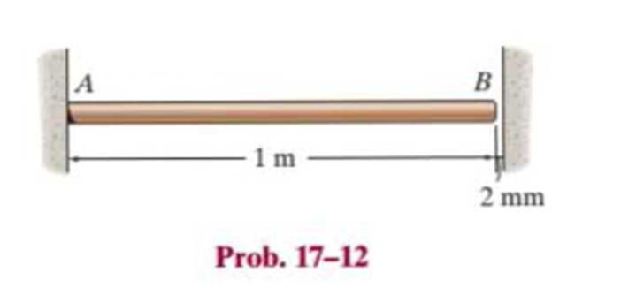
The 50-mm-diameter C86100 bronze rod is fixed supported at A and has a gap of 2 mm from the wall at B. Determine the increase in temperature ΔT that will cause the rod to buckle. Assume that the contact at B acts as a pin.
Expert Solution & Answer
Want to see the full answer?
Check out a sample textbook solution
Students have asked these similar questions
The 46-mm-diameter C86100 bronze rod is fixed supported at A and has a gap of 2 mm from the wall at B.
Part A
AT =
μÀ
Determine the increase in temperature AT that will cause the rod to buckle. Assume that the contact at B acts as a pin. Use Ebr 103 GPa
Express your answer to three significant figures and include appropriate units.
Value
Submit Request Answer
Units
Im
?
R
2 mm.
The plastic 50-mm diameter rod is placed in a 51-mm-diameter hole with rigid walls. Determine the change in the length of the rod after the 8 kN load is applied. Use E = 40 MPa and v=0.45 for the rod.
A 100-mm-long rod has a diameter of 15 mm. If an axial tensile load of 10 kN is applied to it, determine the change in its diameter. E = 70 GPa, n = 0.35.
Chapter 17 Solutions
Statics and Mechanics of Materials (5th Edition)
Ch. 17.3 - A 50-in.-long steel rod has a diameter of 1 in....Ch. 17.3 - A 12-ft wooden rectangular column has the...Ch. 17.3 - Prob. 3FPCh. 17.3 - A steel pipe is fixed supported at its ends. If it...Ch. 17.3 - Determine the maximum force P that can be...Ch. 17.3 - The A992 steel rod BC has a diameter of 50 mm and...Ch. 17.3 - Determine the critical buckling load for the...Ch. 17.3 - Prob. 2PCh. 17.3 - The aircraft link is made from an A992 steel rod....Ch. 17.3 - Rigid bars AB and BC are pin connected at B. If...
Ch. 17.3 - A 2014-T6 aluminum alloy column has a length of 6...Ch. 17.3 - Prob. 6PCh. 17.3 - Prob. 7PCh. 17.3 - Prob. 8PCh. 17.3 - A steel column has a length of 9 m and is fixed at...Ch. 17.3 - A steel column has a length of 9 m and is pinned...Ch. 17.3 - The A992 steel angle has a cross-sectional area of...Ch. 17.3 - The 50-mm-diameter C86100 bronze rod is fixed...Ch. 17.3 - Determine the maximum load P the frame can support...Ch. 17.3 - Prob. 14PCh. 17.3 - Prob. 15PCh. 17.3 - An A992 steel W200 46 column of length 9 m is...Ch. 17.3 - Prob. 17PCh. 17.3 - Prob. 18PCh. 17.3 - Prob. 19PCh. 17.3 - Prob. 20PCh. 17.3 - Prob. 21PCh. 17.3 - The deck is supported by the two 40-mm-square...Ch. 17.3 - Prob. 23PCh. 17.3 - Prob. 24PCh. 17.3 - Prob. 25PCh. 17.3 - Prob. 26PCh. 17.3 - Prob. 27PCh. 17.3 - The linkage is made using two A992 steel rods,...Ch. 17.3 - The linkage is made using two A-36 steel rods,...Ch. 17.3 - The linkage is made using two A-36 steel rods,...Ch. 17.3 - The steel bar AB has a rectangular cross section....Ch. 17.3 - Determine if the frame can support a load of P =...Ch. 17.3 - Determine the maximum allowable load P that can be...Ch. 17.3 - Prob. 34PCh. 17.3 - Prob. 35PCh. 17.3 - The members of the truss are assumed to be pin...Ch. 17.3 - The members of the truss are assumed to be pin...Ch. 17.3 - The truss is made from A992 steel bars, each of...Ch. 17.3 - The truss is made from A992 steel bars, each of...Ch. 17.3 - The steel bar AB of the frame is assumed to be pin...Ch. 17.3 - Prob. 41PCh. 17.3 - Prob. 42PCh. 17.3 - Prob. 43PCh. 17.3 - Prob. 44PCh. 17.3 - Consider an ideal column as in Fig. 1710d, having...Ch. 17.4 - Prob. 46PCh. 17.4 - Prob. 47PCh. 17.4 - The W10 12 structural A-36 steel column is used...Ch. 17.4 - The aluminum column is fixed at the bottom and...Ch. 17.4 - Prob. 50PCh. 17.4 - The aluminum rod is fixed at its base and free and...Ch. 17.4 - Prob. 52PCh. 17.4 - Prob. 53PCh. 17.4 - Prob. 54PCh. 17.4 - The wood column is pinned at its base and top....Ch. 17.4 - Prob. 56PCh. 17.4 - Prob. 57PCh. 17.4 - Prob. 58PCh. 17.4 - Prob. 59PCh. 17.4 - Prob. 60PCh. 17.4 - Prob. 61PCh. 17.4 - Prob. 62PCh. 17.4 - The W14 53 column is fixed at its base and free...Ch. 17.4 - Prob. 64PCh. 17 - The wood column is 4 m long and is required to...Ch. 17 - Prob. 2RPCh. 17 - A steel column has a length of 5 m and is free at...Ch. 17 - Prob. 4RPCh. 17 - Prob. 5RPCh. 17 - If P = 15 kip, determine the required minimum...Ch. 17 - Prob. 7RPCh. 17 - The W200 46 wide-flange A992-steel column can be...Ch. 17 - The wide-flange A992 steel column has the cross...Ch. 17 - The wide-flange A992 steel column has the cross...
Knowledge Booster


Learn more about
Need a deep-dive on the concept behind this application? Look no further. Learn more about this topic, mechanical-engineering and related others by exploring similar questions and additional content below.Similar questions
- Determine the maximum force P that can be applied to the handle so that the steel control rod AB does not buckle. The rod has a diameter of 0.25 m. It is pin connected at .its ends. E = 100 MPa )2.5 نقطة( 3m 2 m A 3 marrow_forwardThe three steel wires are used to support the load. If the wires have an allowable tensile stress of σallow = 165 MPa, and wire AB has a diameter of 5 mm, wire BD has a diameter of 7 mm and wire BC has a diameter of 6 mm. Determine the maximum force P that can be applied before one of the wires fails.arrow_forwardThe A-36 steel pipe has an outer diameter of 2 in. If it is held in place by a guywire, determine its required inner diameter to the nearest 1 8 in., so that it can support a maximum vertical load of P = 4 kip without causing the pipe to buckle. Assume the ends of the pipe are pin connected.arrow_forward
- The rigid pipe is supported by a pin at A and an A-36 steel guy wire BD. If the wire has a diameter of 0.25 in., determine how much it stretches when a load of P = 600 lb acts on the pipe.arrow_forwardTwo metal bars are fastened together at the bolted flange connection shown. There are 2 total bolts connecting the two metal bars together and each bolt has diameter dbolt 12.7 mm. The flange is oriented at angle = 50° with respect to longitudinal axis of the metal bars. If an axial force F = 30 kN is applied as shown, determine the overall safety factor of the bolted connection. You may assume the bolts are made out of 1020HR steel and the strength of the bolt in shear is 50% of the tensile strength of the bolt material. F - SF overall = 0 number (rtol=0.01, at F ?arrow_forwardThe outer is constructed from a 34 mm steel spring and measures 240 mm in diameter with 10 active coils. The smaller of the two concentric helical springs is constructed from a steel spring with a diameter of 20 mm and an outside diameter of 90 mm. It contains 12 active coils. The outer spring is 30 mm longer than the inner spring prior to the application of the load. G = 85 Gpa is used. When this nest of springs is subjected to an 80 kN load. Determine each spring's spring rate. (Draw the diagram)arrow_forward
- Each of the two members is made from 6061-T6 aluminum and has a square cross section 1 in. * 1 in. They are pin connected at their ends and a jack is placed between them and opened until the force it exerts on each member is50 lb. Determine the greatest force P that can be applied to the center of the top member without causing either of the two members to yield. For the analysis neglect the axial force in each member. Assume the jack is rigid.arrow_forwardThe linkage is made using two A-36 steel rods, each having a circular cross section. Determine the diameter of each rod to the nearest 1 8 in. that will support the 900-lb load. Assume that the rods are pin connected at their ends. Use a factor of safety with respect to buckling of F.S. = 1.8.arrow_forwardThe post is made from 606l-T6 aluminum and has a diameter of 50 mm. It is fixed supported at A and B, and at its center C there is a coiled spring attached to the rigid collar. If the spring is originally uncompressed, determine the compression in the spring when the load of P = 50 kN is applied to the collar.arrow_forward
- The A-36 steel pipe has an outer radius of 20 mm and an inner radius of 15 mm. If it fits snugly between the fixed walls before it is loaded, determine the reaction at the walls when it is subjected to the load shown.arrow_forwardThe bar is made of a 2014-T6 aluminum alloy. Determine its smallest thickness b if its width is 5b. Assume that it is pin connected at its ends.arrow_forwardload of 12 kN is raised by means of a screw jack. The mean diameter of the square threaded screw is 48 mm and the pitch is 12 mm. A force of 180 N is applied at the end of a lever to raise the load. Determine the length of the lever to be used and the mechanical advantage obtained. the screw self-locking? Take µ = 0.12.arrow_forward
arrow_back_ios
SEE MORE QUESTIONS
arrow_forward_ios
Recommended textbooks for you
 Elements Of ElectromagneticsMechanical EngineeringISBN:9780190698614Author:Sadiku, Matthew N. O.Publisher:Oxford University Press
 Mechanics of Materials (10th Edition)Mechanical EngineeringISBN:9780134319650Author:Russell C. HibbelerPublisher:PEARSON
 Thermodynamics: An Engineering ApproachMechanical EngineeringISBN:9781259822674Author:Yunus A. Cengel Dr., Michael A. BolesPublisher:McGraw-Hill Education
 Control Systems EngineeringMechanical EngineeringISBN:9781118170519Author:Norman S. NisePublisher:WILEY
 Mechanics of Materials (MindTap Course List)Mechanical EngineeringISBN:9781337093347Author:Barry J. Goodno, James M. GerePublisher:Cengage Learning
 Engineering Mechanics: StaticsMechanical EngineeringISBN:9781118807330Author:James L. Meriam, L. G. Kraige, J. N. BoltonPublisher:WILEY
Elements Of Electromagnetics
Mechanical Engineering
ISBN:9780190698614
Author:Sadiku, Matthew N. O.
Publisher:Oxford University Press
Mechanics of Materials (10th Edition)
Mechanical Engineering
ISBN:9780134319650
Author:Russell C. Hibbeler
Publisher:PEARSON
Thermodynamics: An Engineering Approach
Mechanical Engineering
ISBN:9781259822674
Author:Yunus A. Cengel Dr., Michael A. Boles
Publisher:McGraw-Hill Education
Control Systems Engineering
Mechanical Engineering
ISBN:9781118170519
Author:Norman S. Nise
Publisher:WILEY
Mechanics of Materials (MindTap Course List)
Mechanical Engineering
ISBN:9781337093347
Author:Barry J. Goodno, James M. Gere
Publisher:Cengage Learning
Engineering Mechanics: Statics
Mechanical Engineering
ISBN:9781118807330
Author:James L. Meriam, L. G. Kraige, J. N. Bolton
Publisher:WILEY
EVERYTHING on Axial Loading Normal Stress in 10 MINUTES - Mechanics of Materials; Author: Less Boring Lectures;https://www.youtube.com/watch?v=jQ-fNqZWrNg;License: Standard YouTube License, CC-BY