
Electronics Fundamentals: Circuits, Devices & Applications
8th Edition
ISBN: 9780135072950
Author: Thomas L. Floyd, David Buchla
Publisher: Prentice Hall
expand_more
expand_more
format_list_bulleted
Concept explainers
Videos
Textbook Question
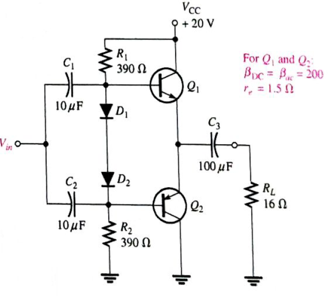
Chapter 17, Problem 25P
Determine the maximum peak output voltage and peak load current for the circuit in Figure 17-78.
Expert Solution & Answer
Want to see the full answer?
Check out a sample textbook solution
Students have asked these similar questions
what is the Rin, Rout, gain in given figure
The upper cutoff frequency of this amplifoer is 22KHz. The output at that frequency is 6.71V p-p. What is the output voltage of 220kHz.
Find the delay angle of 1 phase half wave converter has 120V supply rms voltage with the value of the resistor is 10Ohm. The average output voltage is 25% of the maximum possible output voltage then find the delay angle.
Chapter 17 Solutions
Electronics Fundamentals: Circuits, Devices & Applications
Ch. 17 - In a bipolar transistor, if the base-emitter...Ch. 17 - When a transistor is saturated. an increase in...Ch. 17 - Prob. 3TFQCh. 17 - The power gain of a CC amplifier is the same as...Ch. 17 - A class B amplifier is more efficient than a class...Ch. 17 - A JFET is always operated with the gate-source...Ch. 17 - Prob. 7TFQCh. 17 - The transconductance of a FET is the ratio of ac...Ch. 17 - Prob. 9TFQCh. 17 - The input to a feedback oscillator is only the...
Ch. 17 - The n-type regions in an npn bipolar junction...Ch. 17 - The n-region in a pnp transistor is the base...Ch. 17 - Prob. 3STCh. 17 - Prob. 4STCh. 17 - Prob. 5STCh. 17 - Alpha () is the ratio of collector current to...Ch. 17 - If the beta of a certain transistor operating in...Ch. 17 - If the base current of a transistor operating in...Ch. 17 - Prob. 9STCh. 17 - When the gate-to-source voltage of an n-channel...Ch. 17 - When a negative gate-to-source voltage is applied...Ch. 17 - Prob. 12STCh. 17 - If the capacitor from emitter to ground in a CE...Ch. 17 - When the collector resistor in a CE amplifier is...Ch. 17 - The input resistance of a CE amplifier is affected...Ch. 17 - The output signal of a CE amplifier is always in...Ch. 17 - The output signal of a common-collector amplifier...Ch. 17 - The largest theoretical voltage gain obtainable...Ch. 17 - In a class A amplifier, the output signal is...Ch. 17 - A class A amplifier conducts for 90 of input cycle...Ch. 17 - Prob. 21STCh. 17 - Feedback oscillators operate on the principle of...Ch. 17 - What is the value of IC for IE=5.34mA and IB=475A?Ch. 17 - Prob. 2PCh. 17 - Prob. 3PCh. 17 - In a certain transistor circuit, the base current...Ch. 17 - Find IB,IE, and in Figure 17-70 given that DC=0.98...Ch. 17 - The transistor in Figure 17-70 is replaced with...Ch. 17 - Prob. 7PCh. 17 - Prob. 8PCh. 17 - Determine IB,IC, and VC in Figure 17-72.Ch. 17 - For the circuit in Figure 17-73, find VB,VE,IE,IC,...Ch. 17 - In Figure 17-73, what is VCE? What are the Q-point...Ch. 17 - A transistor amplifier has a voltage gain of 50....Ch. 17 - To achieve an output of 10 V with an input of300...Ch. 17 - A 50 mV signal is applied to the base of a...Ch. 17 - Determine the voltage gain for Figure 17-74.Ch. 17 - Determine each of the dc voltages, VB,VC, and VE,...Ch. 17 - Determine the following dc values for the...Ch. 17 - Determine the following ac values for the...Ch. 17 - The amplifier in Figure 17-76 has a variable gain...Ch. 17 - If a load resistance of 600 is placed on the...Ch. 17 - Determine the voltage gain for the...Ch. 17 - What is the total input resistance in Figure...Ch. 17 - A load resistance is capacitively coupled in the...Ch. 17 - Prob. 24PCh. 17 - Determine the maximum peak output voltage and peak...Ch. 17 - The efficiency of a certain class B push-pull...Ch. 17 - Prob. 27PCh. 17 - The transistor in Figure 17-80 has a DC of 150....Ch. 17 - The VGS of ap-channel JFET is increased from 1 V...Ch. 17 - Why must the gate-to-source voltage of an...Ch. 17 - Draw the schematic symbols for n-channel and...Ch. 17 - Explain why both types of MOSFETs have an...Ch. 17 - In what mode is an n-channel D-MOSFET operating...Ch. 17 - A certain E-MOSFET has a VGS(th)=3V. What is the...Ch. 17 - For each circuit in Figure 17-81, determine VDS...Ch. 17 - Prob. 36PCh. 17 - Each E-MOSFET in Figure 17-83 has a VGS(th) of +5...Ch. 17 - Prob. 38PCh. 17 - Find the gain of each amplifier in Figure 17-85.Ch. 17 - Determine the gain of each amplifier in Figure...Ch. 17 - If the voltage gain of the amplifier portion of a...Ch. 17 - Generally describe the change required to the...Ch. 17 - Prob. 43PCh. 17 - Prob. 44PCh. 17 - Prob. 47PCh. 17 - Prob. 48PCh. 17 - Prob. 49PCh. 17 - Prob. 50PCh. 17 - Prob. 51PCh. 17 - Prob. 52PCh. 17 - Open file P17-53. Determine if the circuit is...
Knowledge Booster


Learn more about
Need a deep-dive on the concept behind this application? Look no further. Learn more about this topic, electrical-engineering and related others by exploring similar questions and additional content below.Similar questions
- Briefly explain about Resonant CCM Boost Converter, zero current switching (ZCS) and zero voltage switching (ZVS)arrow_forwardThe positive peak value of output waveform for the given circuit diagram is. Bias voltage is 2 V, Diode is germanium) (VPP of input is 18 V, V VouTarrow_forwardQ/ Why is high frequency (Fsw ) used in Buck Converter circuitsarrow_forward
- A single phase fully controlled bridge converter supplies a load drawing constant and ripple free load current, if the triggering angle is 30°, the input power factor will bearrow_forward20Vp Vout 9V 15V Draw output wave for this circuit mentioning maximum and minimum peak voltagesarrow_forwardC/ Calculate load regulation of 7805 regulator has full load output voltage of 5.15 * V and no-load output voltage is 5.18 Varrow_forward
- In small-signal FETS, the DC voltage sources will be replaced by a Short circuit Current source O Open circuit Resistorarrow_forwardConsider the following figure. Represent the discrete samples into their corresponding hex values. Draw the analog signal. Image below:arrow_forward2. Draw and explain the difference between clipper circuit and clamper circuit output waveformarrow_forward
- single phase full controlled bridge converter uses a. 4 SCRs and 2 diodes b. 4 SCRs c. 6 SCRs d. 4 SCRs and 2 diodesarrow_forwardWhat is the noise figure when the input signal and the noise values are 200 and 20uW and the output signal and noise values are 2 and 0.8 W?arrow_forwardPICmicro A/D converter is configured for 0 to 5v range and is right justified. When analog input voltage of 0.93 volts is applied, what value in decimal will be stored in ADRESL.arrow_forward
arrow_back_ios
SEE MORE QUESTIONS
arrow_forward_ios
Recommended textbooks for you
 Introductory Circuit Analysis (13th Edition)Electrical EngineeringISBN:9780133923605Author:Robert L. BoylestadPublisher:PEARSON
 Delmar's Standard Textbook Of ElectricityElectrical EngineeringISBN:9781337900348Author:Stephen L. HermanPublisher:Cengage Learning
 Programmable Logic ControllersElectrical EngineeringISBN:9780073373843Author:Frank D. PetruzellaPublisher:McGraw-Hill Education
 Fundamentals of Electric CircuitsElectrical EngineeringISBN:9780078028229Author:Charles K Alexander, Matthew SadikuPublisher:McGraw-Hill Education
 Electric Circuits. (11th Edition)Electrical EngineeringISBN:9780134746968Author:James W. Nilsson, Susan RiedelPublisher:PEARSON
 Engineering ElectromagneticsElectrical EngineeringISBN:9780078028151Author:Hayt, William H. (william Hart), Jr, BUCK, John A.Publisher:Mcgraw-hill Education,
Introductory Circuit Analysis (13th Edition)
Electrical Engineering
ISBN:9780133923605
Author:Robert L. Boylestad
Publisher:PEARSON
Delmar's Standard Textbook Of Electricity
Electrical Engineering
ISBN:9781337900348
Author:Stephen L. Herman
Publisher:Cengage Learning
Programmable Logic Controllers
Electrical Engineering
ISBN:9780073373843
Author:Frank D. Petruzella
Publisher:McGraw-Hill Education
Fundamentals of Electric Circuits
Electrical Engineering
ISBN:9780078028229
Author:Charles K Alexander, Matthew Sadiku
Publisher:McGraw-Hill Education
Electric Circuits. (11th Edition)
Electrical Engineering
ISBN:9780134746968
Author:James W. Nilsson, Susan Riedel
Publisher:PEARSON
Engineering Electromagnetics
Electrical Engineering
ISBN:9780078028151
Author:Hayt, William H. (william Hart), Jr, BUCK, John A.
Publisher:Mcgraw-hill Education,
Multistage Transistor Audio Amplifier Circuit; Author: The Organic Chemistry Tutor;https://www.youtube.com/watch?v=LJrL9N9uhkE;License: Standard Youtube License